
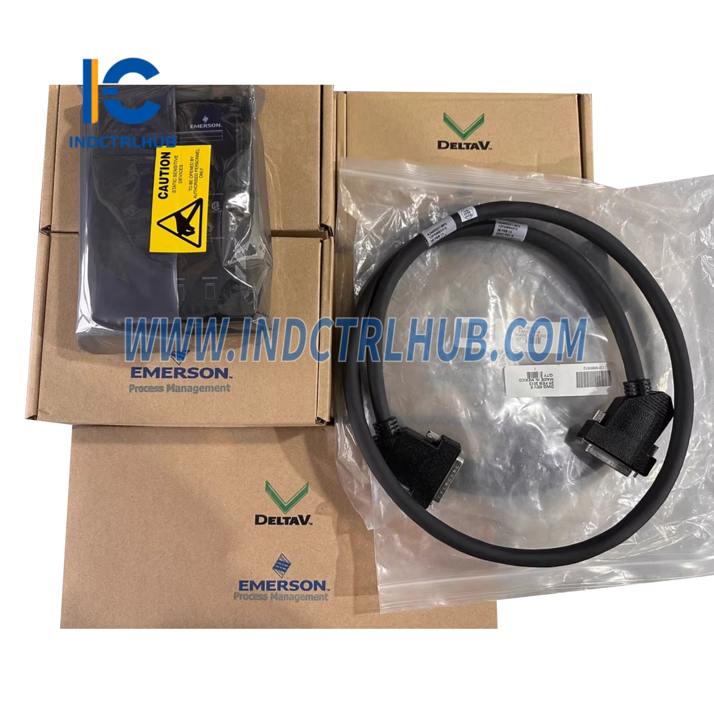
Emerson KJ4002X1-BE1 Top Extender Cable Assembly
Emerson KJ4002X1-BE1 Top Extender Cable Assembly
Manufacturer: Emerson
Product No.: KJ4002X1-BE1
Condition:1000 in stock
Product Type: DeltaV Interconnect Cable
Product Origin: 8962990997763
Payment: T/T, Western Union
Weight: 1000g
Shipping port: Xiamen
Warranty: 12 months
- 24/7 Support
- 30-Day Returns
- Fast Shipping
Emerson KJ4002X1-BE1 Top Extender Cable Assembly - DeltaV Upward LocalBus Expansion
The Emerson KJ4002X1-BE1 Top Extender Cable Assembly enables upward vertical expansion of DeltaV distributed control system I/O architectures, providing LocalBus connectivity for mounting I/O carriers above existing installations. This top-mount extender cable delivers 12.6VDC at 15A for reliable power and high-speed communication distribution, supporting flexible cabinet layouts in oil & gas, chemical, pharmaceutical, and power generation facilities where upward I/O expansion optimizes space utilization and system organization.
Core Technical Specifications
- Model Number: KJ4002X1-BE1 (Top Extender configuration)
- Configuration: Top extender cable assembly for upward vertical I/O expansion
- LocalBus Power: 12.6VDC at 15A maximum current capacity
- Operating Temperature: -40°C to +70°C (-40°F to 158°F)
- Maximum System Length: 6.5 meters combined (I/O carriers + LocalBus extenders)
- Environmental Protection: IP20 rating with ISA-S71.04-1985 Class G3 conformal coating
- System Compatibility: DeltaV M-series and S-series controllers with I/O carriers
Global Hazardous Area Certifications
Certified for deployment in classified industrial environments worldwide:
- FM/CSA North America: Class I, Division 2, Groups A-D, T4; Class I, Zone 2 applications
- ATEX Europe: Zone 2 certified for explosive atmosphere installations per Document 12P2046
- IECEx International: Compliant with global hazardous area standards
- Marine Certification: DNV and ABS approved for offshore platforms and maritime installations
Industrial System Architecture Applications
Vertical Cabinet Space Optimization: Mount additional I/O carriers above existing DeltaV installations to maximize vertical cabinet space utilization. The top extender configuration is ideal for control rooms with limited floor space but available vertical clearance, enabling system capacity expansion without adding new cabinets or relocating existing equipment.
Phased System Expansions: Support incremental DCS capacity additions during plant upgrades or production line expansions. Add new I/O carriers above existing installations without disrupting operational systems, minimizing downtime during turnarounds and enabling staged commissioning of new process areas.
Process Area Segregation: Organize I/O carriers by process unit or functional area within tall marshalling cabinets. Mount safety-critical I/O at eye level for easy visual inspection while placing less frequently accessed I/O points in upper cabinet positions, improving operational efficiency and maintenance accessibility.
Retrofit Installations: Integrate new DeltaV I/O into existing control systems where bottom-mount expansion is constrained by cable routing, power distribution, or physical obstructions. Top extenders provide alternative expansion paths when conventional bottom-mount configurations are impractical.
Multi-Level Control Rooms: Connect I/O carriers across different vertical levels within multi-story control buildings or mezzanine installations. When properly routed through conduit, top extenders enable LocalBus connectivity between floor levels while maintaining the 6.5-meter total system length requirement.
Top Extender vs. Bottom Extender Selection
Strategic considerations for choosing upward or downward expansion:
| Configuration | Best Applications | Advantages |
|---|---|---|
| Top Extender (BE1) | Limited floor space, overhead clearance available, retrofit expansions | Preserves lower cabinet space for cable routing, easier access to base equipment |
| Bottom Extender (BF series) | Standard installations, gravity-assisted cable routing, conventional layouts | Natural cable drape, easier field termination access, traditional architecture |
LocalBus System Architecture Benefits
Critical advantages for DeltaV I/O expansion and system flexibility:
- Bidirectional Expansion: Combine top and bottom extenders for maximum cabinet utilization and flexible I/O placement
- Simplified Power Distribution: Single cable assembly provides both 12.6VDC power and high-speed communication
- Reduced Installation Complexity: Pre-assembled cable eliminates field termination errors and accelerates commissioning
- Scalable Architecture: Add I/O capacity incrementally without controller upgrades or system redesigns
- Hot-Swap Support: Replace failed carriers without disrupting adjacent I/O (when properly configured in non-hazardous areas)
Installation Requirements & Best Practices
Critical guidelines for reliable LocalBus operation:
Maximum System Length Compliance: The combined length of all I/O carriers and LocalBus extender cables must not exceed 6.5 meters. This includes physical carrier dimensions plus all extender cable lengths in the LocalBus chain. Exceeding this limit causes communication errors, power delivery issues, and system instability.
Mandatory Conduit Protection: All interconnecting cables between separate enclosures MUST be installed in conduit for mechanical protection and EMC compliance. This requirement applies to both hazardous and non-hazardous installations to prevent cable damage, maintain signal integrity, and meet electrical code requirements.
Power Budget Calculation: Calculate total I/O module power consumption to ensure it remains within the 12.6VDC at 15A LocalBus capacity. High-density analog modules, HART-enabled CHARMs, and smart transmitter interfaces consume more power than discrete I/O, requiring careful system planning to avoid LocalBus overload.
Cable Routing & Support: Provide adequate cable support for top extenders to prevent strain on connectors and maintain proper cable bend radius. Unlike bottom extenders where gravity assists cable routing, top extenders require mechanical support to prevent cable sag and connector stress over time.
Grounding & Shield Continuity: Maintain proper cabinet grounding and LocalBus shield continuity throughout the cable chain. Improper grounding introduces ground loops, common mode noise, and communication errors, particularly in installations with multiple cabinets or long cable runs near high-power equipment.
Hazardous Area Installation Requirements
Critical safety guidelines for classified locations:
- Installation Documentation: Comply with Document 12P2046 "DeltaV Scalable Process System Zone 2 Installation Instructions" and "Installing Your DeltaV Automation System" manual
- De-Energized Installation: DO NOT insert or remove extender cables while system power is energized unless area is verified non-hazardous
- Energy Isolation Verification: Disconnect LocalBus power and verify zero energy state before cable installation or removal in classified areas
- Conduit Requirements: Inter-enclosure cables require rigid or flexible conduit rated for the area classification and environmental conditions
Environmental Specifications
| Parameter | Specification |
|---|---|
| Operating Temperature | -40°C to +70°C (-40°F to 158°F) |
| Shock Resistance | 10g ½-sinewave for 11ms |
| Vibration Tolerance | 1mm peak-to-peak (5-16 Hz); 0.5g (16-150 Hz) |
| Humidity Range | 5% to 95% non-condensing |
| Airborne Contaminants | ISA-S71.04-1985 Class G3 protection |
| IP Rating | IP20 (control room environment) |
System Planning Considerations
Critical factors for successful DeltaV I/O expansion:
- Vertical Clearance: Verify adequate overhead clearance for top-mounted carriers including cable routing space and maintenance access
- Cable Management: Plan cable routing paths that minimize bend radius violations and provide strain relief for upward cable runs
- Accessibility: Consider maintenance access requirements for upper-mounted I/O carriers including ladder or platform needs
- Future Expansion: Reserve additional vertical space for potential future I/O additions to avoid premature cabinet capacity limits
- Load Distribution: Balance I/O carrier weight distribution to prevent cabinet tipping or structural stress
Why Choose Industrial Control Hub?
Your specialized source for genuine Emerson DeltaV automation components:
- ✓ 100% authentic OEM products with full manufacturer traceability and warranty
- ✓ Expert DCS technical support from certified automation engineers
- ✓ Extensive inventory of current production and legacy DeltaV interconnect cables
- ✓ Expedited global shipping to US, UK, EU, and Asia-Pacific markets
- ✓ Competitive pricing with volume discounts for project quantities
- ✓ Complete documentation, installation drawings, and system design assistance
Complementary DeltaV LocalBus Components
| Product Model | Description | Link |
|---|---|---|
| KJ4002X1-BF2 | Bottom Extender Cable Assembly for downward vertical I/O expansion | View Product |
| KJ4010X1-BF1 | Left LocalBus Extender Cable Assembly (12P0831X062) for horizontal expansion | View Product |
| VE4050E1C0 | DeltaV 8-Wide I/O Interface Carrier for mounting I/O cards and CHARMs | View Product |
Ordering Information & System Planning
- KJ4002X1-BE1: Top Extender Cable Assembly (this product)
- Alternative Configurations: Bottom extenders (BF1/BF2/BF3/BF4) for downward expansion
- System Planning: Calculate total carrier dimensions + cable lengths to ensure ≤6.5m total system length
- Power Budget: Verify total I/O module consumption remains within 12.6VDC @ 15A LocalBus capacity
Technical Documentation & Support
Complete installation manuals including Document 12P2046 (Zone 2 Installation Instructions) and "Installing Your DeltaV Automation System" available upon request. Our application engineering team provides system architecture consultation, LocalBus length calculations, power budget analysis, and cabinet layout design assistance for complex DeltaV expansions including upward vertical configurations.
Maintenance & Service Life
- No User-Serviceable Parts: Factory-assembled cable with sealed connectors requires no field maintenance
- No Calibration Required: Digital communication protocol eliminates drift and calibration requirements
- Do Not Disassemble: Connector disassembly voids warranty and may compromise signal integrity
- Replacement Criteria: Replace if physical damage, connector wear, or communication errors occur
- Periodic Inspection: Verify cable support integrity and connector tightness during scheduled maintenance
© 2025 INDUSTRIAL CONTROL HUB. All rights reserved.
Original Source: https://www.indctrlhub.com
Contact: sales@indctrlhub.com | +0086 18359243191
Product Description
Emerson KJ4002X1-BE1 Top Extender Cable Assembly - DeltaV Upward LocalBus Expansion
The Emerson KJ4002X1-BE1 Top Extender Cable Assembly enables upward vertical expansion of DeltaV distributed control system I/O architectures, providing LocalBus connectivity for mounting I/O carriers above existing installations. This top-mount extender cable delivers 12.6VDC at 15A for reliable power and high-speed communication distribution, supporting flexible cabinet layouts in oil & gas, chemical, pharmaceutical, and power generation facilities where upward I/O expansion optimizes space utilization and system organization.
Core Technical Specifications
- Model Number: KJ4002X1-BE1 (Top Extender configuration)
- Configuration: Top extender cable assembly for upward vertical I/O expansion
- LocalBus Power: 12.6VDC at 15A maximum current capacity
- Operating Temperature: -40°C to +70°C (-40°F to 158°F)
- Maximum System Length: 6.5 meters combined (I/O carriers + LocalBus extenders)
- Environmental Protection: IP20 rating with ISA-S71.04-1985 Class G3 conformal coating
- System Compatibility: DeltaV M-series and S-series controllers with I/O carriers
Global Hazardous Area Certifications
Certified for deployment in classified industrial environments worldwide:
- FM/CSA North America: Class I, Division 2, Groups A-D, T4; Class I, Zone 2 applications
- ATEX Europe: Zone 2 certified for explosive atmosphere installations per Document 12P2046
- IECEx International: Compliant with global hazardous area standards
- Marine Certification: DNV and ABS approved for offshore platforms and maritime installations
Industrial System Architecture Applications
Vertical Cabinet Space Optimization: Mount additional I/O carriers above existing DeltaV installations to maximize vertical cabinet space utilization. The top extender configuration is ideal for control rooms with limited floor space but available vertical clearance, enabling system capacity expansion without adding new cabinets or relocating existing equipment.
Phased System Expansions: Support incremental DCS capacity additions during plant upgrades or production line expansions. Add new I/O carriers above existing installations without disrupting operational systems, minimizing downtime during turnarounds and enabling staged commissioning of new process areas.
Process Area Segregation: Organize I/O carriers by process unit or functional area within tall marshalling cabinets. Mount safety-critical I/O at eye level for easy visual inspection while placing less frequently accessed I/O points in upper cabinet positions, improving operational efficiency and maintenance accessibility.
Retrofit Installations: Integrate new DeltaV I/O into existing control systems where bottom-mount expansion is constrained by cable routing, power distribution, or physical obstructions. Top extenders provide alternative expansion paths when conventional bottom-mount configurations are impractical.
Multi-Level Control Rooms: Connect I/O carriers across different vertical levels within multi-story control buildings or mezzanine installations. When properly routed through conduit, top extenders enable LocalBus connectivity between floor levels while maintaining the 6.5-meter total system length requirement.
Top Extender vs. Bottom Extender Selection
Strategic considerations for choosing upward or downward expansion:
| Configuration | Best Applications | Advantages |
|---|---|---|
| Top Extender (BE1) | Limited floor space, overhead clearance available, retrofit expansions | Preserves lower cabinet space for cable routing, easier access to base equipment |
| Bottom Extender (BF series) | Standard installations, gravity-assisted cable routing, conventional layouts | Natural cable drape, easier field termination access, traditional architecture |
LocalBus System Architecture Benefits
Critical advantages for DeltaV I/O expansion and system flexibility:
- Bidirectional Expansion: Combine top and bottom extenders for maximum cabinet utilization and flexible I/O placement
- Simplified Power Distribution: Single cable assembly provides both 12.6VDC power and high-speed communication
- Reduced Installation Complexity: Pre-assembled cable eliminates field termination errors and accelerates commissioning
- Scalable Architecture: Add I/O capacity incrementally without controller upgrades or system redesigns
- Hot-Swap Support: Replace failed carriers without disrupting adjacent I/O (when properly configured in non-hazardous areas)
Installation Requirements & Best Practices
Critical guidelines for reliable LocalBus operation:
Maximum System Length Compliance: The combined length of all I/O carriers and LocalBus extender cables must not exceed 6.5 meters. This includes physical carrier dimensions plus all extender cable lengths in the LocalBus chain. Exceeding this limit causes communication errors, power delivery issues, and system instability.
Mandatory Conduit Protection: All interconnecting cables between separate enclosures MUST be installed in conduit for mechanical protection and EMC compliance. This requirement applies to both hazardous and non-hazardous installations to prevent cable damage, maintain signal integrity, and meet electrical code requirements.
Power Budget Calculation: Calculate total I/O module power consumption to ensure it remains within the 12.6VDC at 15A LocalBus capacity. High-density analog modules, HART-enabled CHARMs, and smart transmitter interfaces consume more power than discrete I/O, requiring careful system planning to avoid LocalBus overload.
Cable Routing & Support: Provide adequate cable support for top extenders to prevent strain on connectors and maintain proper cable bend radius. Unlike bottom extenders where gravity assists cable routing, top extenders require mechanical support to prevent cable sag and connector stress over time.
Grounding & Shield Continuity: Maintain proper cabinet grounding and LocalBus shield continuity throughout the cable chain. Improper grounding introduces ground loops, common mode noise, and communication errors, particularly in installations with multiple cabinets or long cable runs near high-power equipment.
Hazardous Area Installation Requirements
Critical safety guidelines for classified locations:
- Installation Documentation: Comply with Document 12P2046 "DeltaV Scalable Process System Zone 2 Installation Instructions" and "Installing Your DeltaV Automation System" manual
- De-Energized Installation: DO NOT insert or remove extender cables while system power is energized unless area is verified non-hazardous
- Energy Isolation Verification: Disconnect LocalBus power and verify zero energy state before cable installation or removal in classified areas
- Conduit Requirements: Inter-enclosure cables require rigid or flexible conduit rated for the area classification and environmental conditions
Environmental Specifications
| Parameter | Specification |
|---|---|
| Operating Temperature | -40°C to +70°C (-40°F to 158°F) |
| Shock Resistance | 10g ½-sinewave for 11ms |
| Vibration Tolerance | 1mm peak-to-peak (5-16 Hz); 0.5g (16-150 Hz) |
| Humidity Range | 5% to 95% non-condensing |
| Airborne Contaminants | ISA-S71.04-1985 Class G3 protection |
| IP Rating | IP20 (control room environment) |
System Planning Considerations
Critical factors for successful DeltaV I/O expansion:
- Vertical Clearance: Verify adequate overhead clearance for top-mounted carriers including cable routing space and maintenance access
- Cable Management: Plan cable routing paths that minimize bend radius violations and provide strain relief for upward cable runs
- Accessibility: Consider maintenance access requirements for upper-mounted I/O carriers including ladder or platform needs
- Future Expansion: Reserve additional vertical space for potential future I/O additions to avoid premature cabinet capacity limits
- Load Distribution: Balance I/O carrier weight distribution to prevent cabinet tipping or structural stress
Why Choose Industrial Control Hub?
Your specialized source for genuine Emerson DeltaV automation components:
- ✓ 100% authentic OEM products with full manufacturer traceability and warranty
- ✓ Expert DCS technical support from certified automation engineers
- ✓ Extensive inventory of current production and legacy DeltaV interconnect cables
- ✓ Expedited global shipping to US, UK, EU, and Asia-Pacific markets
- ✓ Competitive pricing with volume discounts for project quantities
- ✓ Complete documentation, installation drawings, and system design assistance
Complementary DeltaV LocalBus Components
| Product Model | Description | Link |
|---|---|---|
| KJ4002X1-BF2 | Bottom Extender Cable Assembly for downward vertical I/O expansion | View Product |
| KJ4010X1-BF1 | Left LocalBus Extender Cable Assembly (12P0831X062) for horizontal expansion | View Product |
| VE4050E1C0 | DeltaV 8-Wide I/O Interface Carrier for mounting I/O cards and CHARMs | View Product |
Ordering Information & System Planning
- KJ4002X1-BE1: Top Extender Cable Assembly (this product)
- Alternative Configurations: Bottom extenders (BF1/BF2/BF3/BF4) for downward expansion
- System Planning: Calculate total carrier dimensions + cable lengths to ensure ≤6.5m total system length
- Power Budget: Verify total I/O module consumption remains within 12.6VDC @ 15A LocalBus capacity
Technical Documentation & Support
Complete installation manuals including Document 12P2046 (Zone 2 Installation Instructions) and "Installing Your DeltaV Automation System" available upon request. Our application engineering team provides system architecture consultation, LocalBus length calculations, power budget analysis, and cabinet layout design assistance for complex DeltaV expansions including upward vertical configurations.
Maintenance & Service Life
- No User-Serviceable Parts: Factory-assembled cable with sealed connectors requires no field maintenance
- No Calibration Required: Digital communication protocol eliminates drift and calibration requirements
- Do Not Disassemble: Connector disassembly voids warranty and may compromise signal integrity
- Replacement Criteria: Replace if physical damage, connector wear, or communication errors occur
- Periodic Inspection: Verify cable support integrity and connector tightness during scheduled maintenance
© 2025 INDUSTRIAL CONTROL HUB. All rights reserved.
Original Source: https://www.indctrlhub.com
Contact: sales@indctrlhub.com | +0086 18359243191