

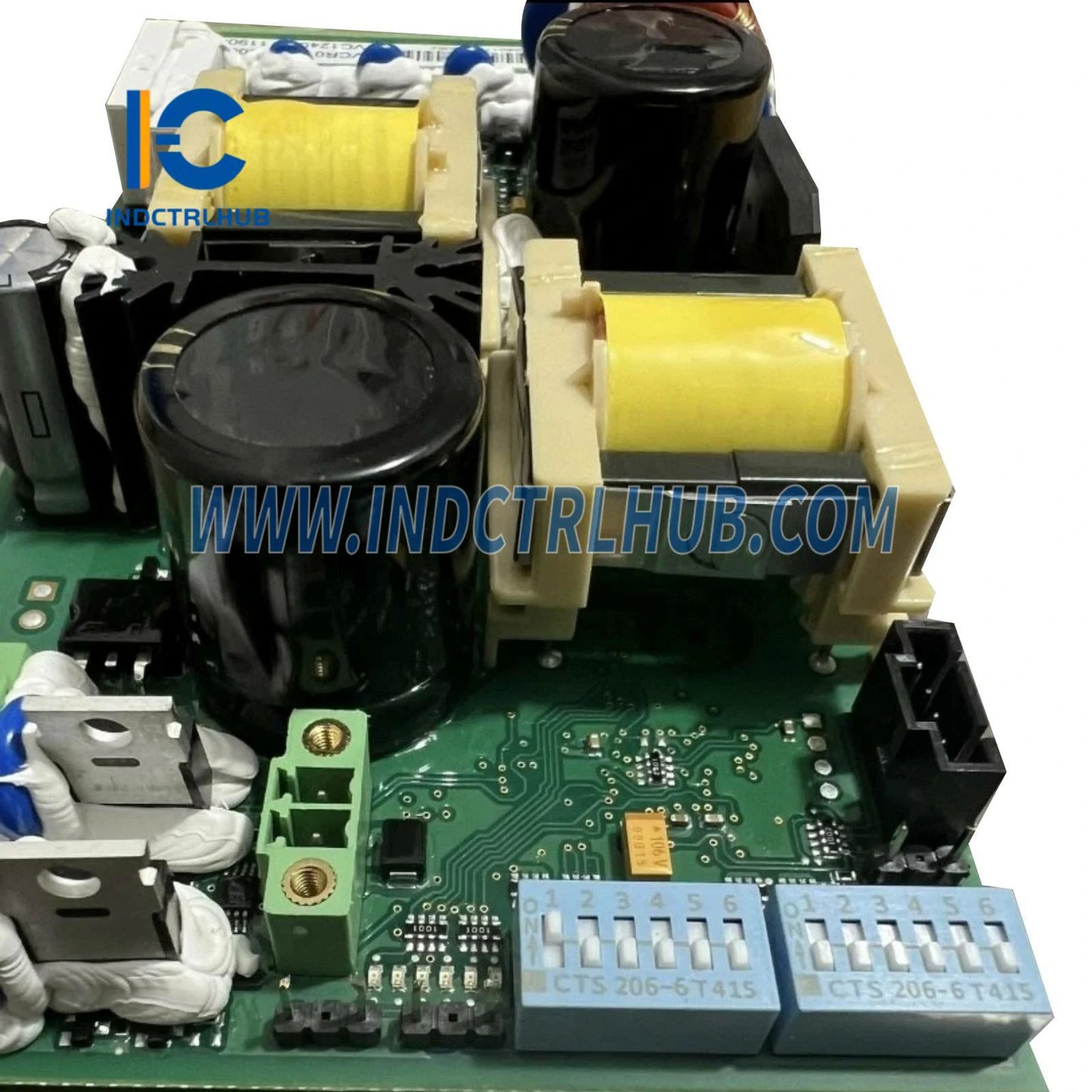
1VCR017053G0006 | ABB VSC Vacuum Contactor Control Board
1VCR017053G0006 | ABB VSC Vacuum Contactor Control Board
Manufacturer: ABB
Product No.: 1VCR017053G0006
Condition:1000 in stock
Product Type: Vacuum Contactor Control Board
Product Origin: 1017053000013
Payment: T/T, Western Union
Weight: 1000g
Shipping port: Xiamen
Warranty: 12 months
- 24/7 Support
- 30-Day Returns
- Fast Shipping
ABB VSC Vacuum Contactor Control Board - Precision Medium-Voltage Switching Control
The ABB 1VCR017053G0006 represents a critical control interface engineered specifically for ABB V-Contact VSC series vacuum contactors operating in medium-voltage industrial environments. This intelligent control board delivers reliable power management, signal processing, and protection coordination for demanding motor control, capacitor switching, and load isolation applications where operational integrity is paramount.
Engineering Advantages
- Medium-Voltage Capability: Designed for VSC contactors handling up to 7.2 kV switching operations in industrial distribution systems
- Integrated Protection: Built-in overvoltage protection, EMI filtering, and galvanic isolation safeguard control circuits from transient disturbances
- Universal Control Interface: 24VDC nominal operation compatible with standard industrial control systems and PLCs
- Thermal Resilience: -25°C to +70°C operating range ensures reliable performance in non-climate-controlled switchgear environments
- Compliance Certified: IEC 62271-100 and CE marked for global medium-voltage switchgear installations
- Retrofit Compatible: Direct replacement board for existing ABB VSC vacuum contactor installations, minimizing downtime
Technical Specifications
| Specification | Value |
|---|---|
| Manufacturer | ABB |
| Part Number | 1VCR017053G0006 |
| Product Category | Vacuum Contactor Control Board |
| Compatible Series | ABB V-Contact VSC vacuum contactors |
| Voltage Rating (Contactor) | Up to 7.2 kV (medium voltage) |
| Control Voltage | 24 VDC nominal (18-30 VDC operating range) |
| Control Current Draw | ≤500 mA @ 24 VDC (typical) |
| Switching Frequency | Up to 1200 operations/hour (motor duty) |
| Contact Life Expectancy | 1-3 million operations (load dependent) |
| Response Time | Closing: 50-80 ms, Opening: 30-60 ms (typical) |
| Isolation Voltage | 2.5 kV control-to-power circuit isolation |
| EMC Compliance | EN 61000-6-2 (immunity), EN 61000-6-4 (emissions) |
| Operating Temperature | -25°C to +70°C |
| Storage Temperature | -40°C to +85°C |
| Humidity Tolerance | 5-95% RH, non-condensing |
| Altitude Rating | Up to 2000m without derating |
| Mounting Type | Panel mount within contactor enclosure |
| Dimensions (W×H×D) | 160 mm × 100 mm × 50 mm (approximate) |
| Weight | 0.5 kg |
| Connection Type | Screw terminals and plug connectors |
| Protection Class | IP20 (when installed in enclosure) |
| Standards Compliance | IEC 62271-100, IEC 60947, CE, UL |
Functional Architecture & Operation
Power Supply Management
The control board incorporates a regulated power supply circuit that accepts 18-30 VDC input and provides stable voltage rails for microcontroller operation, relay drivers, and signal conditioning circuits. Internal voltage regulation ensures consistent performance despite fluctuations in the external control power source, critical for installations powered by battery-backed UPS systems or solar-charged DC buses.
Coil Drive Circuitry
High-current MOSFET drivers energize the vacuum contactor's electromagnetic coil with precisely controlled current profiles. The board implements soft-start algorithms to reduce inrush current and mechanical shock during closing operations, extending contactor mechanical life. Holding current optimization reduces power dissipation by 40-60% after initial pull-in, minimizing thermal stress in continuous-duty applications.
Auxiliary Contact Interface
Provides signal conditioning and isolation for auxiliary contacts (NO/NC) used in interlock circuits, status indication, and PLC feedback. Optical isolation (2.5 kV) prevents ground loops and protects sensitive control equipment from voltage transients induced during high-voltage switching events. Compatible with both dry contact and wet contact (24-48 VDC) signaling schemes.
Protection & Diagnostics
Integrated protection features include:
- Overvoltage Protection: Crowbar circuit clamps transients above 35 VDC to protect semiconductor components
- Reverse Polarity Protection: Series diode prevents damage from incorrect wiring during installation
- Thermal Monitoring: On-board temperature sensor triggers shutdown if board temperature exceeds 85°C
- Coil Continuity Detection: Monitors coil resistance to detect open-circuit faults before energization
- EMI Filtering: Pi-filter network on control inputs attenuates conducted emissions per EN 61000-6-4
Industrial Application Use Cases
1. Medium-Voltage Motor Control Centers (MCC)
In industrial facilities operating 4.16 kV or 6.6 kV motors (compressors, pumps, fans, mills), the VSC control board manages contactor switching for DOL (Direct-On-Line) starting and stopping. The board's fast response time enables integration with soft-start controllers and variable frequency drives for coordinated motor protection. Typical applications include:
- Cement plant kiln drive systems (2-5 MW motors)
- Water treatment high-service pumps (500-2000 HP)
- Mining conveyor and crusher motors (1-3 MW)
- HVAC chiller compressors in large commercial buildings
2. Capacitor Bank Switching
Power factor correction systems in industrial plants and utility substations rely on vacuum contactors for capacitor bank switching. The VSC control board's synchronized closing capability (when paired with appropriate controllers) minimizes inrush current and extends capacitor life. The board supports:
- Fixed capacitor banks (300-3000 kVAR per stage)
- Automatic power factor correction systems with 6-12 switching stages
- Harmonic filter banks in facilities with non-linear loads (VFDs, rectifiers)
- Reactive power compensation in wind farms and solar inverter stations
3. Load Transfer & Bus Sectionalizing
In critical power distribution systems requiring automatic or manual load transfer between sources (utility/generator, dual feeders), VSC contactors with this control board provide reliable isolation and switching. Applications include:
- Hospital emergency power systems (NFPA 99 compliance)
- Data center dual-feed switchgear with automatic transfer schemes
- Industrial microgrid islanding and synchronization controls
- Utility substation bus-tie and sectionalizing switches
4. Arc Furnace & Welding Equipment
High-current, high-cycle applications in steel mills and fabrication shops demand robust contactor control. The VSC board's high switching frequency rating (1200 ops/hour) and thermal management support:
- Electric arc furnace electrode positioning systems
- Resistance welding transformer primary switching
- Induction heating equipment power control
- Electroplating rectifier load management
5. Renewable Energy Integration
Solar farms and wind installations use vacuum contactors for inverter isolation, transformer switching, and grid interconnection. The control board's wide temperature range (-25°C to +70°C) suits outdoor enclosures in desert and arctic climates. Specific applications:
- PV inverter AC disconnect switching (1-2 MW inverters)
- Wind turbine generator contactor control (2-5 MW turbines)
- Battery energy storage system (BESS) isolation contactors
- Medium-voltage collector system sectionalizing
Installation & System Integration
Pre-Installation Requirements
- Compatibility Verification: Confirm VSC contactor model number matches control board specification (consult ABB cross-reference table)
- Control Power Source: Ensure 24 VDC supply can deliver 1A continuous (2A peak during coil energization)
- Environmental Assessment: Verify ambient temperature within -25°C to +70°C range, provide ventilation if enclosed
- Wiring Preparation: Use 18 AWG (1.0 mm²) minimum for control circuits, 14 AWG (2.5 mm²) for coil power
- Grounding: Establish low-impedance ground connection to switchgear frame (≤1 ohm resistance)
Installation Procedure
- De-energize System: Verify zero voltage on all circuits using calibrated test equipment, apply lockout/tagout
- Remove Existing Board: Disconnect all wiring (photograph connections for reference), remove mounting screws
- Inspect Mounting Surface: Clean mounting area, verify no debris or moisture in enclosure
- Install New Board: Align mounting holes, secure with M4 screws torqued to 1.2 Nm
- Connect Control Power: Wire 24 VDC supply to designated terminals (observe polarity markings)
- Connect Coil Circuit: Attach coil power leads to output terminals (typically labeled A1/A2)
- Wire Auxiliary Contacts: Connect NO/NC contacts to PLC or control panel per schematic
- Ground Connection: Bond board ground terminal to switchgear PE with 14 AWG wire
- Visual Inspection: Verify all connections tight, no loose strands, proper wire routing away from high-voltage components
- Functional Test: Apply control power, verify LED indicators (if present), test close/open commands with contactor de-energized
- Commissioning: Energize contactor, perform 10 close/open cycles, measure coil current and verify within specification
Integration with Control Systems
The VSC control board interfaces with various automation platforms:
- PLC Integration: Digital outputs (24 VDC sink/source) drive close/open commands, digital inputs monitor auxiliary contact status
- SCADA Systems: RTU or gateway modules translate Modbus/DNP3 commands to discrete I/O signals for board control
- Motor Protection Relays: ABB REF615, Siemens 7SJ, SEL-710 relays provide trip/close signals based on overcurrent, ground fault, or thermal conditions
- Synchronizing Controllers: For paralleling applications, sync-check relays (ABB SYNCHROTACT) coordinate closing with voltage/phase matching
- Manual Control: Hardwired pushbutton stations with maintained contact or momentary pulse operation
Troubleshooting & Preventive Maintenance
Common Issues & Solutions
| Symptom | Probable Cause | Corrective Action |
|---|---|---|
| Contactor fails to close | No control power, open coil circuit, board fault | Verify 24 VDC present at board input, check coil continuity (typically 50-200Ω), inspect board for burnt components |
| Contactor closes but drops out | Insufficient holding current, low control voltage, mechanical binding | Measure coil voltage under load (should be ≥20 VDC), check for mechanical obstructions, verify board output current |
| Auxiliary contacts not functioning | Wiring error, contact wear, isolation failure | Verify wiring per schematic, test contact resistance (should be <0.1Ω closed, >10MΩ open), check for arc damage |
| Erratic operation / nuisance trips | EMI interference, loose connections, ground loops | Install ferrite cores on control cables, re-torque all terminals, verify single-point grounding |
| Board overheating | Excessive ambient temperature, inadequate ventilation, high switching frequency | Improve enclosure cooling, reduce duty cycle, verify ambient ≤70°C |
| LED indicators not illuminating | Control power absent, board internal fault | Check 24 VDC supply voltage and current capacity, replace board if power present but no LED |
Preventive Maintenance Schedule
- Monthly: Visual inspection for signs of overheating (discoloration), verify LED status, check terminal tightness
- Quarterly: Measure control voltage under load, inspect wiring insulation for degradation, clean dust from enclosure
- Annually: Perform insulation resistance test (500 VDC megger, expect >100 MΩ), verify auxiliary contact operation, document switching cycle count
- Every 3 Years: Thermographic scan of board and connections under load, replace if hot spots detected (>10°C above ambient)
- Every 5 Years: Consider board replacement as preventive measure (electrolytic capacitor aging), especially in high-cycle applications
Spare Parts Strategy
For critical installations, maintain one spare control board per 5-10 contactors in service. Store in climate-controlled environment (15-25°C, <60% RH) in anti-static packaging. Rotate spares into service every 3 years to prevent shelf-life degradation of electrolytic components. Document board serial numbers and installation dates for traceability.
Safety Considerations & Compliance
Electrical Safety
- Qualified Personnel Only: Installation and maintenance must be performed by electricians trained in medium-voltage systems
- Arc Flash Hazard: Contactor switching operations can generate arc flash energy; follow NFPA 70E guidelines for PPE selection
- Lockout/Tagout: Always de-energize and verify zero voltage before accessing control board or contactor internals
- Isolation Distance: Maintain minimum 300 mm clearance from energized medium-voltage components during maintenance
- Grounding: Verify protective earth continuity before energization; ground resistance should be <1 ohm
Regulatory Compliance
- IEC 62271-100: High-voltage switchgear and controlgear - Part 100: Alternating current circuit-breakers
- IEC 60947-4-1: Low-voltage switchgear - Part 4-1: Contactors and motor-starters - Electromechanical contactors
- EN 61000-6-2: EMC immunity standard for industrial environments
- EN 61000-6-4: EMC emission standard for industrial environments
- UL 347: High-voltage industrial control equipment (North American installations)
- CSA C22.2 No. 14: Industrial control equipment (Canadian installations)
- CE Marking: Compliant with EU Low Voltage Directive 2014/35/EU and EMC Directive 2014/30/EU
Technical Documentation & Support
Comprehensive engineering resources available for the VSC control board:
- Installation Manual: Step-by-step procedures with wiring diagrams and torque specifications (Document: 1VCR017053-IM-EN)
- Technical Datasheet: Electrical characteristics, environmental ratings, and dimensional drawings
- Application Guide: Motor control, capacitor switching, and load transfer application notes
- Compatibility Matrix: Cross-reference table for VSC contactor models and control board variants
- Spare Parts Catalog: Replacement components and accessories with ordering information
- Firmware Updates: Not applicable (hardware-based control, no programmable firmware)
For application engineering support, warranty inquiries, or technical assistance, contact our team using the information provided below.
Warranty & Quality Assurance
Every ABB VSC control board undergoes comprehensive factory testing:
- 100% functional test with simulated coil load and auxiliary contact verification
- High-voltage isolation test (2.5 kV control-to-power, 1 minute duration)
- EMC pre-compliance testing for emissions and immunity per EN 61000 series
- Thermal cycling test (-25°C to +70°C, 5 cycles) to verify solder joint integrity
- Burn-in test (48 hours at 60°C ambient with cyclic loading) to eliminate infant mortality failures
Standard warranty is 24 months from date of shipment. Extended warranty programs and advance replacement services are available for critical applications. All boards are manufactured in ISO 9001:2015 and ISO 14001:2015 certified facilities with full component traceability and RoHS compliance documentation.

Product Description
ABB VSC Vacuum Contactor Control Board - Precision Medium-Voltage Switching Control
The ABB 1VCR017053G0006 represents a critical control interface engineered specifically for ABB V-Contact VSC series vacuum contactors operating in medium-voltage industrial environments. This intelligent control board delivers reliable power management, signal processing, and protection coordination for demanding motor control, capacitor switching, and load isolation applications where operational integrity is paramount.
Engineering Advantages
- Medium-Voltage Capability: Designed for VSC contactors handling up to 7.2 kV switching operations in industrial distribution systems
- Integrated Protection: Built-in overvoltage protection, EMI filtering, and galvanic isolation safeguard control circuits from transient disturbances
- Universal Control Interface: 24VDC nominal operation compatible with standard industrial control systems and PLCs
- Thermal Resilience: -25°C to +70°C operating range ensures reliable performance in non-climate-controlled switchgear environments
- Compliance Certified: IEC 62271-100 and CE marked for global medium-voltage switchgear installations
- Retrofit Compatible: Direct replacement board for existing ABB VSC vacuum contactor installations, minimizing downtime
Technical Specifications
| Specification | Value |
|---|---|
| Manufacturer | ABB |
| Part Number | 1VCR017053G0006 |
| Product Category | Vacuum Contactor Control Board |
| Compatible Series | ABB V-Contact VSC vacuum contactors |
| Voltage Rating (Contactor) | Up to 7.2 kV (medium voltage) |
| Control Voltage | 24 VDC nominal (18-30 VDC operating range) |
| Control Current Draw | ≤500 mA @ 24 VDC (typical) |
| Switching Frequency | Up to 1200 operations/hour (motor duty) |
| Contact Life Expectancy | 1-3 million operations (load dependent) |
| Response Time | Closing: 50-80 ms, Opening: 30-60 ms (typical) |
| Isolation Voltage | 2.5 kV control-to-power circuit isolation |
| EMC Compliance | EN 61000-6-2 (immunity), EN 61000-6-4 (emissions) |
| Operating Temperature | -25°C to +70°C |
| Storage Temperature | -40°C to +85°C |
| Humidity Tolerance | 5-95% RH, non-condensing |
| Altitude Rating | Up to 2000m without derating |
| Mounting Type | Panel mount within contactor enclosure |
| Dimensions (W×H×D) | 160 mm × 100 mm × 50 mm (approximate) |
| Weight | 0.5 kg |
| Connection Type | Screw terminals and plug connectors |
| Protection Class | IP20 (when installed in enclosure) |
| Standards Compliance | IEC 62271-100, IEC 60947, CE, UL |
Functional Architecture & Operation
Power Supply Management
The control board incorporates a regulated power supply circuit that accepts 18-30 VDC input and provides stable voltage rails for microcontroller operation, relay drivers, and signal conditioning circuits. Internal voltage regulation ensures consistent performance despite fluctuations in the external control power source, critical for installations powered by battery-backed UPS systems or solar-charged DC buses.
Coil Drive Circuitry
High-current MOSFET drivers energize the vacuum contactor's electromagnetic coil with precisely controlled current profiles. The board implements soft-start algorithms to reduce inrush current and mechanical shock during closing operations, extending contactor mechanical life. Holding current optimization reduces power dissipation by 40-60% after initial pull-in, minimizing thermal stress in continuous-duty applications.
Auxiliary Contact Interface
Provides signal conditioning and isolation for auxiliary contacts (NO/NC) used in interlock circuits, status indication, and PLC feedback. Optical isolation (2.5 kV) prevents ground loops and protects sensitive control equipment from voltage transients induced during high-voltage switching events. Compatible with both dry contact and wet contact (24-48 VDC) signaling schemes.
Protection & Diagnostics
Integrated protection features include:
- Overvoltage Protection: Crowbar circuit clamps transients above 35 VDC to protect semiconductor components
- Reverse Polarity Protection: Series diode prevents damage from incorrect wiring during installation
- Thermal Monitoring: On-board temperature sensor triggers shutdown if board temperature exceeds 85°C
- Coil Continuity Detection: Monitors coil resistance to detect open-circuit faults before energization
- EMI Filtering: Pi-filter network on control inputs attenuates conducted emissions per EN 61000-6-4
Industrial Application Use Cases
1. Medium-Voltage Motor Control Centers (MCC)
In industrial facilities operating 4.16 kV or 6.6 kV motors (compressors, pumps, fans, mills), the VSC control board manages contactor switching for DOL (Direct-On-Line) starting and stopping. The board's fast response time enables integration with soft-start controllers and variable frequency drives for coordinated motor protection. Typical applications include:
- Cement plant kiln drive systems (2-5 MW motors)
- Water treatment high-service pumps (500-2000 HP)
- Mining conveyor and crusher motors (1-3 MW)
- HVAC chiller compressors in large commercial buildings
2. Capacitor Bank Switching
Power factor correction systems in industrial plants and utility substations rely on vacuum contactors for capacitor bank switching. The VSC control board's synchronized closing capability (when paired with appropriate controllers) minimizes inrush current and extends capacitor life. The board supports:
- Fixed capacitor banks (300-3000 kVAR per stage)
- Automatic power factor correction systems with 6-12 switching stages
- Harmonic filter banks in facilities with non-linear loads (VFDs, rectifiers)
- Reactive power compensation in wind farms and solar inverter stations
3. Load Transfer & Bus Sectionalizing
In critical power distribution systems requiring automatic or manual load transfer between sources (utility/generator, dual feeders), VSC contactors with this control board provide reliable isolation and switching. Applications include:
- Hospital emergency power systems (NFPA 99 compliance)
- Data center dual-feed switchgear with automatic transfer schemes
- Industrial microgrid islanding and synchronization controls
- Utility substation bus-tie and sectionalizing switches
4. Arc Furnace & Welding Equipment
High-current, high-cycle applications in steel mills and fabrication shops demand robust contactor control. The VSC board's high switching frequency rating (1200 ops/hour) and thermal management support:
- Electric arc furnace electrode positioning systems
- Resistance welding transformer primary switching
- Induction heating equipment power control
- Electroplating rectifier load management
5. Renewable Energy Integration
Solar farms and wind installations use vacuum contactors for inverter isolation, transformer switching, and grid interconnection. The control board's wide temperature range (-25°C to +70°C) suits outdoor enclosures in desert and arctic climates. Specific applications:
- PV inverter AC disconnect switching (1-2 MW inverters)
- Wind turbine generator contactor control (2-5 MW turbines)
- Battery energy storage system (BESS) isolation contactors
- Medium-voltage collector system sectionalizing
Installation & System Integration
Pre-Installation Requirements
- Compatibility Verification: Confirm VSC contactor model number matches control board specification (consult ABB cross-reference table)
- Control Power Source: Ensure 24 VDC supply can deliver 1A continuous (2A peak during coil energization)
- Environmental Assessment: Verify ambient temperature within -25°C to +70°C range, provide ventilation if enclosed
- Wiring Preparation: Use 18 AWG (1.0 mm²) minimum for control circuits, 14 AWG (2.5 mm²) for coil power
- Grounding: Establish low-impedance ground connection to switchgear frame (≤1 ohm resistance)
Installation Procedure
- De-energize System: Verify zero voltage on all circuits using calibrated test equipment, apply lockout/tagout
- Remove Existing Board: Disconnect all wiring (photograph connections for reference), remove mounting screws
- Inspect Mounting Surface: Clean mounting area, verify no debris or moisture in enclosure
- Install New Board: Align mounting holes, secure with M4 screws torqued to 1.2 Nm
- Connect Control Power: Wire 24 VDC supply to designated terminals (observe polarity markings)
- Connect Coil Circuit: Attach coil power leads to output terminals (typically labeled A1/A2)
- Wire Auxiliary Contacts: Connect NO/NC contacts to PLC or control panel per schematic
- Ground Connection: Bond board ground terminal to switchgear PE with 14 AWG wire
- Visual Inspection: Verify all connections tight, no loose strands, proper wire routing away from high-voltage components
- Functional Test: Apply control power, verify LED indicators (if present), test close/open commands with contactor de-energized
- Commissioning: Energize contactor, perform 10 close/open cycles, measure coil current and verify within specification
Integration with Control Systems
The VSC control board interfaces with various automation platforms:
- PLC Integration: Digital outputs (24 VDC sink/source) drive close/open commands, digital inputs monitor auxiliary contact status
- SCADA Systems: RTU or gateway modules translate Modbus/DNP3 commands to discrete I/O signals for board control
- Motor Protection Relays: ABB REF615, Siemens 7SJ, SEL-710 relays provide trip/close signals based on overcurrent, ground fault, or thermal conditions
- Synchronizing Controllers: For paralleling applications, sync-check relays (ABB SYNCHROTACT) coordinate closing with voltage/phase matching
- Manual Control: Hardwired pushbutton stations with maintained contact or momentary pulse operation
Troubleshooting & Preventive Maintenance
Common Issues & Solutions
| Symptom | Probable Cause | Corrective Action |
|---|---|---|
| Contactor fails to close | No control power, open coil circuit, board fault | Verify 24 VDC present at board input, check coil continuity (typically 50-200Ω), inspect board for burnt components |
| Contactor closes but drops out | Insufficient holding current, low control voltage, mechanical binding | Measure coil voltage under load (should be ≥20 VDC), check for mechanical obstructions, verify board output current |
| Auxiliary contacts not functioning | Wiring error, contact wear, isolation failure | Verify wiring per schematic, test contact resistance (should be <0.1Ω closed, >10MΩ open), check for arc damage |
| Erratic operation / nuisance trips | EMI interference, loose connections, ground loops | Install ferrite cores on control cables, re-torque all terminals, verify single-point grounding |
| Board overheating | Excessive ambient temperature, inadequate ventilation, high switching frequency | Improve enclosure cooling, reduce duty cycle, verify ambient ≤70°C |
| LED indicators not illuminating | Control power absent, board internal fault | Check 24 VDC supply voltage and current capacity, replace board if power present but no LED |
Preventive Maintenance Schedule
- Monthly: Visual inspection for signs of overheating (discoloration), verify LED status, check terminal tightness
- Quarterly: Measure control voltage under load, inspect wiring insulation for degradation, clean dust from enclosure
- Annually: Perform insulation resistance test (500 VDC megger, expect >100 MΩ), verify auxiliary contact operation, document switching cycle count
- Every 3 Years: Thermographic scan of board and connections under load, replace if hot spots detected (>10°C above ambient)
- Every 5 Years: Consider board replacement as preventive measure (electrolytic capacitor aging), especially in high-cycle applications
Spare Parts Strategy
For critical installations, maintain one spare control board per 5-10 contactors in service. Store in climate-controlled environment (15-25°C, <60% RH) in anti-static packaging. Rotate spares into service every 3 years to prevent shelf-life degradation of electrolytic components. Document board serial numbers and installation dates for traceability.
Safety Considerations & Compliance
Electrical Safety
- Qualified Personnel Only: Installation and maintenance must be performed by electricians trained in medium-voltage systems
- Arc Flash Hazard: Contactor switching operations can generate arc flash energy; follow NFPA 70E guidelines for PPE selection
- Lockout/Tagout: Always de-energize and verify zero voltage before accessing control board or contactor internals
- Isolation Distance: Maintain minimum 300 mm clearance from energized medium-voltage components during maintenance
- Grounding: Verify protective earth continuity before energization; ground resistance should be <1 ohm
Regulatory Compliance
- IEC 62271-100: High-voltage switchgear and controlgear - Part 100: Alternating current circuit-breakers
- IEC 60947-4-1: Low-voltage switchgear - Part 4-1: Contactors and motor-starters - Electromechanical contactors
- EN 61000-6-2: EMC immunity standard for industrial environments
- EN 61000-6-4: EMC emission standard for industrial environments
- UL 347: High-voltage industrial control equipment (North American installations)
- CSA C22.2 No. 14: Industrial control equipment (Canadian installations)
- CE Marking: Compliant with EU Low Voltage Directive 2014/35/EU and EMC Directive 2014/30/EU
Technical Documentation & Support
Comprehensive engineering resources available for the VSC control board:
- Installation Manual: Step-by-step procedures with wiring diagrams and torque specifications (Document: 1VCR017053-IM-EN)
- Technical Datasheet: Electrical characteristics, environmental ratings, and dimensional drawings
- Application Guide: Motor control, capacitor switching, and load transfer application notes
- Compatibility Matrix: Cross-reference table for VSC contactor models and control board variants
- Spare Parts Catalog: Replacement components and accessories with ordering information
- Firmware Updates: Not applicable (hardware-based control, no programmable firmware)
For application engineering support, warranty inquiries, or technical assistance, contact our team using the information provided below.
Warranty & Quality Assurance
Every ABB VSC control board undergoes comprehensive factory testing:
- 100% functional test with simulated coil load and auxiliary contact verification
- High-voltage isolation test (2.5 kV control-to-power, 1 minute duration)
- EMC pre-compliance testing for emissions and immunity per EN 61000 series
- Thermal cycling test (-25°C to +70°C, 5 cycles) to verify solder joint integrity
- Burn-in test (48 hours at 60°C ambient with cyclic loading) to eliminate infant mortality failures
Standard warranty is 24 months from date of shipment. Extended warranty programs and advance replacement services are available for critical applications. All boards are manufactured in ISO 9001:2015 and ISO 14001:2015 certified facilities with full component traceability and RoHS compliance documentation.