
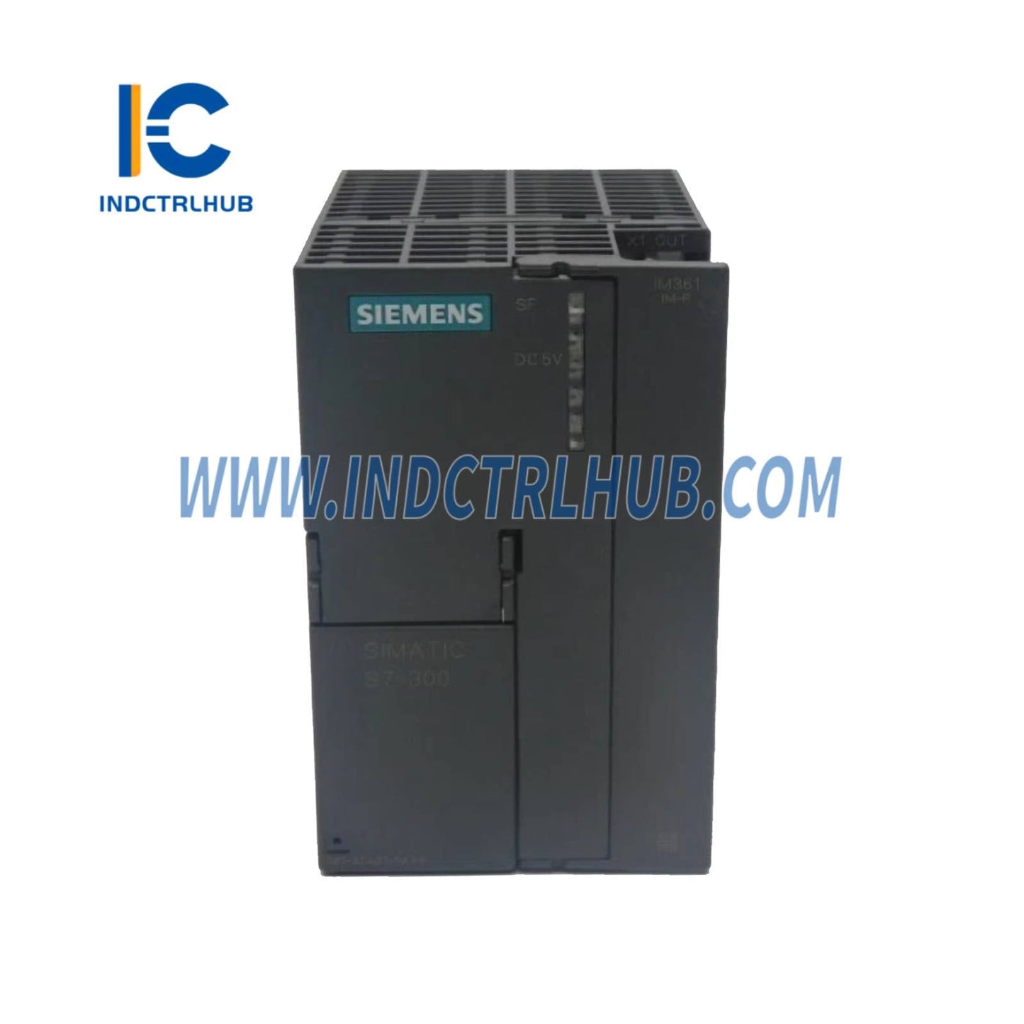
Siemens 6ES7361-3CA01-0AA0 Interface Module IM 361 for S7-300 Redundant Systems
Siemens 6ES7361-3CA01-0AA0 Interface Module IM 361 for S7-300 Redundant Systems
Manufacturer: Siemens
Product No.: 6ES7361-3CA01-0AA0
Condition:1000 in stock
Product Type: Interface Modules
Product Origin: 4019169006675
Payment: T/T, Western Union
Weight: 1000g
Shipping port: Xiamen
Warranty: 12 months
- 24/7 Support
- 30-Day Returns
- Fast Shipping
🔗 Siemens 6ES7361-3CA01-0AA0 IM 361 Interface Module
Redundant Communication for Mission-Critical S7-300 Automation
🛡️ Why IM 361 Matters for Your Operation
In industries where downtime costs thousands per minute—pharmaceutical manufacturing, power generation, oil & gas—a single point of failure is unacceptable. The Siemens 6ES7361-3CA01-0AA0 IM 361 delivers redundant interface communication between S7-300 central and expansion racks, ensuring your automation system stays online even if one communication path fails.
Real-World Impact: A European chemical plant avoided €2.3M in lost production by implementing IM 361 redundancy when a cable fault occurred during peak production. The system seamlessly switched to the backup path with zero process interruption.
📐 Complete Technical Specifications
| Parameter | Specification | Notes |
|---|---|---|
| Order Number | 6ES7361-3CA01-0AA0 | Official Siemens part number |
| Module Type | IM 361 Interface Module | Redundant variant of IM 360 |
| System Compatibility | SIMATIC S7-300 (all CPUs) | Requires CPU with redundancy support |
| Max Expansion Racks | 3 expansion racks | 4 racks total (1 central + 3 expansion) |
| Redundancy Type | Dual communication paths | Automatic failover on cable/module fault |
| Connection Interface | 2× IM 365 cable ports | Requires paired IM 365 cables (sold separately) |
| Data Transfer Rate | 1.5 Mbps per path | Synchronized dual-channel transmission |
| Switchover Time | <100ms typical | Transparent to application logic |
| Power Consumption | 3W typ. from 5V DC backplane | Higher than IM 360 due to dual circuits |
| Mounting Position | Slot 3 (central & expansion) | Fixed position per S7-300 architecture |
| Operating Temperature | 0°C to +60°C | Horizontal mounting (derate for vertical) |
| Humidity Tolerance | 5% to 95% RH (non-condensing) | Conformal coating for harsh environments |
| Vibration Resistance | IEC 60068-2-6 (10-58 Hz, 0.075mm) | Suitable for mobile machinery |
| Certifications | CE, UL508, cULus, FM, ATEX, IECEx | Global compliance for hazardous areas |
| MTBF | >150,000 hours | Calculated per SN 29500 standard |
| Dimensions (W×H×D) | 40mm × 125mm × 120mm | Single-width S7-300 module |
| Weight | 280g approx. | Slightly heavier than IM 360 |
| LED Indicators | SF (red), BF1/BF2 (red), RUN (green) | Dual BF LEDs for each communication path |
🏗️ System Architecture Design
Typical Redundant Configuration
┌─────────────────────────────────────────────────────────────┐
│                    CENTRAL RACK (Slot 3)                    │
│  ┌──────────────────────────────────────────────────────┐   │
│  │         IM 361 (6ES7361-3CA01-0AA0)                  │   │
│  │  [Path A Port] ════════════╗  [Path B Port]          │   │
│  └────────────────────────────║───────────────────────────┘   │
└────────────────────────────────║───────────────────────────────┘
                                 ║
              IM 365 Cable A ════╬════ IM 365 Cable B
                                 ║
┌────────────────────────────────║───────────────────────────────┐
│                 EXPANSION RACK 1 (Slot 3)                     │
│  ┌────────────────────────────║───────────────────────────┐   │
│  │  [Path A Port] ════════════╝  [Path B Port]            │   │
│  │         IM 361 (6ES7361-3CA01-0AA0)                    │   │
│  └──────────────────────────────────────────────────────┘   │
└─────────────────────────────────────────────────────────────┘
Key Design Principles:
- ✅ Always use paired IM 365 cables of identical length (1m, 2.5m, 5m, or 10m)
- ✅ Route cables through separate cable trays to avoid common-mode failures
- ✅ Install IM 361 modules in both central and expansion racks
- ✅ Ensure proper EMC grounding of cable shields at both ends
- ⚠️ Do NOT mix IM 360 and IM 361 in the same rack chain
🎯 Mission-Critical Applications
🏥 Pharmaceutical Clean Room Control
Challenge: FDA-regulated sterile production requires 99.99% uptime with full audit trails.
Solution: IM 361 redundancy ensures HVAC, pressure differential, and particle monitoring systems remain operational during maintenance or cable damage.
Result: Zero unplanned shutdowns over 3-year validation period.
⚡ Power Substation Automation
Challenge: Circuit breaker control and protection relays cannot tolerate communication loss.
Solution: Dual IM 361 paths provide fault-tolerant I/O connectivity for critical switchgear monitoring.
Result: Meets IEC 61850 reliability requirements for Tier 1 substations.
🛢️ Offshore Oil Platform
Challenge: Harsh marine environment with vibration, salt fog, and limited maintenance access.
Solution: IM 361's conformal coating and redundant design withstands corrosive conditions while maintaining safety system integrity.
Result: 5+ years continuous operation in North Sea platform.
⚖️ IM 361 vs. IM 360: Which Do You Need?
| Criteria | IM 360 (Standard) | IM 361 (Redundant) ✅ |
|---|---|---|
| Communication Paths | Single | Dual (redundant) |
| Failover Capability | ❌ None | ✅ Automatic (<100ms) |
| Typical Use Case | Non-critical machinery | Safety systems, continuous processes |
| Cost Premium | Baseline | +40% approx. |
| Power Consumption | 1.5W | 3W (dual circuits) |
| Cable Requirement | 1× IM 365 cable | 2× IM 365 cables (paired) |
| Recommended For | Packaging, assembly lines | Pharma, energy, chemical, water treatment |
💡 Decision Rule: If your downtime cost exceeds $1,000/hour, IM 361 redundancy pays for itself in the first prevented outage.
🔧 Installation & Commissioning Checklist
Pre-Installation
- ☐ Verify CPU supports redundant I/O (check CPU manual)
- ☐ Procure 2× IM 365 cables per rack pair (same length)
- ☐ Plan separate cable routing paths (min. 100mm separation)
- ☐ Confirm Slot 3 availability in all racks
Hardware Installation
- ☐ Power down entire S7-300 system
- ☐ Install IM 361 in Slot 3 of central rack
- ☐ Install IM 361 in Slot 3 of expansion rack
- ☐ Connect Path A cable (top port) between racks
- ☐ Connect Path B cable (bottom port) via alternate route
- ☐ Verify cable shield grounding at both ends
Commissioning
- ☐ Power up central rack, wait for RUN LED (green)
- ☐ Power up expansion rack, verify both BF1 and BF2 LEDs off
- ☐ In STEP 7, configure hardware with IM 361 modules
- ☐ Download configuration to CPU
- ☐ Test failover: disconnect Path A cable → verify BF1 LED on, system continues running
- ☐ Reconnect Path A, disconnect Path B → verify BF2 LED on, system continues running
- ☐ Document cable routing in as-built drawings
🔍 Diagnostic LED Guide
| LED Status | Meaning | Action Required |
|---|---|---|
| 🟢 RUN on, SF off, BF1/BF2 off | Normal operation (both paths active) | None – system healthy |
| 🔴 BF1 on, BF2 off | Path A fault (running on Path B) | Check Path A cable and connections |
| 🔴 BF1 off, BF2 on | Path B fault (running on Path A) | Check Path B cable and connections |
| 🔴 BF1 on, BF2 on | Both paths failed | CRITICAL: Check both cables, module seating, power supply |
| 🔴 SF on | Module hardware fault | Replace IM 361 module (RMA required) |
🔐 Authenticity & Warranty
Industrial Control Hub Commitment:
- ✅ Factory-Direct Sourcing: All IM 361 modules procured from Siemens authorized distributors with full traceability
- ✅ Tamper-Evident Packaging: Original Siemens ESD bags with holographic seals
- ✅ Batch Code Verification: Laser-etched serial numbers verifiable via Siemens Support Portal
- ✅ Warranty Coverage: 12-month manufacturer warranty + optional extended service contracts
- ⚠️ Counterfeit Risk: Non-genuine modules may lack redundancy logic, causing silent failures in critical situations
How to Verify Your Module:
- Check for Siemens logo laser etching (not printed sticker)
- Verify order number 6ES7361-3CA01-0AA0 on module label
- Confirm manufacturing date code (format: YYWW)
- Contact us for Certificate of Conformity (CoC) documentation
📞 Technical Support & Resources
Pre-Sales Consultation:
- 📧 Email: sales@indctrlhub.com (response within 4 hours)
- 💬 Live Chat: Available Mon-Fri 9:00-18:00 CST
- 📞 Phone: +86-183-5924-3191 (Mandarin/English)
Complementary Products:
- 🔗 IM 365 Interface Cables (1m / 2.5m / 5m / 10m) – Required for connection
- 🔌 S7-300 Power Supply Modules (PS 307) – Ensure adequate 5V DC capacity
- 🛡️ Surge Protection Devices – Recommended for outdoor installations
Product Description
🔗 Siemens 6ES7361-3CA01-0AA0 IM 361 Interface Module
Redundant Communication for Mission-Critical S7-300 Automation
🛡️ Why IM 361 Matters for Your Operation
In industries where downtime costs thousands per minute—pharmaceutical manufacturing, power generation, oil & gas—a single point of failure is unacceptable. The Siemens 6ES7361-3CA01-0AA0 IM 361 delivers redundant interface communication between S7-300 central and expansion racks, ensuring your automation system stays online even if one communication path fails.
Real-World Impact: A European chemical plant avoided €2.3M in lost production by implementing IM 361 redundancy when a cable fault occurred during peak production. The system seamlessly switched to the backup path with zero process interruption.
📐 Complete Technical Specifications
| Parameter | Specification | Notes |
|---|---|---|
| Order Number | 6ES7361-3CA01-0AA0 | Official Siemens part number |
| Module Type | IM 361 Interface Module | Redundant variant of IM 360 |
| System Compatibility | SIMATIC S7-300 (all CPUs) | Requires CPU with redundancy support |
| Max Expansion Racks | 3 expansion racks | 4 racks total (1 central + 3 expansion) |
| Redundancy Type | Dual communication paths | Automatic failover on cable/module fault |
| Connection Interface | 2× IM 365 cable ports | Requires paired IM 365 cables (sold separately) |
| Data Transfer Rate | 1.5 Mbps per path | Synchronized dual-channel transmission |
| Switchover Time | <100ms typical | Transparent to application logic |
| Power Consumption | 3W typ. from 5V DC backplane | Higher than IM 360 due to dual circuits |
| Mounting Position | Slot 3 (central & expansion) | Fixed position per S7-300 architecture |
| Operating Temperature | 0°C to +60°C | Horizontal mounting (derate for vertical) |
| Humidity Tolerance | 5% to 95% RH (non-condensing) | Conformal coating for harsh environments |
| Vibration Resistance | IEC 60068-2-6 (10-58 Hz, 0.075mm) | Suitable for mobile machinery |
| Certifications | CE, UL508, cULus, FM, ATEX, IECEx | Global compliance for hazardous areas |
| MTBF | >150,000 hours | Calculated per SN 29500 standard |
| Dimensions (W×H×D) | 40mm × 125mm × 120mm | Single-width S7-300 module |
| Weight | 280g approx. | Slightly heavier than IM 360 |
| LED Indicators | SF (red), BF1/BF2 (red), RUN (green) | Dual BF LEDs for each communication path |
🏗️ System Architecture Design
Typical Redundant Configuration
┌─────────────────────────────────────────────────────────────┐
│                    CENTRAL RACK (Slot 3)                    │
│  ┌──────────────────────────────────────────────────────┐   │
│  │         IM 361 (6ES7361-3CA01-0AA0)                  │   │
│  │  [Path A Port] ════════════╗  [Path B Port]          │   │
│  └────────────────────────────║───────────────────────────┘   │
└────────────────────────────────║───────────────────────────────┘
                                 ║
              IM 365 Cable A ════╬════ IM 365 Cable B
                                 ║
┌────────────────────────────────║───────────────────────────────┐
│                 EXPANSION RACK 1 (Slot 3)                     │
│  ┌────────────────────────────║───────────────────────────┐   │
│  │  [Path A Port] ════════════╝  [Path B Port]            │   │
│  │         IM 361 (6ES7361-3CA01-0AA0)                    │   │
│  └──────────────────────────────────────────────────────┘   │
└─────────────────────────────────────────────────────────────┘
Key Design Principles:
- ✅ Always use paired IM 365 cables of identical length (1m, 2.5m, 5m, or 10m)
- ✅ Route cables through separate cable trays to avoid common-mode failures
- ✅ Install IM 361 modules in both central and expansion racks
- ✅ Ensure proper EMC grounding of cable shields at both ends
- ⚠️ Do NOT mix IM 360 and IM 361 in the same rack chain
🎯 Mission-Critical Applications
🏥 Pharmaceutical Clean Room Control
Challenge: FDA-regulated sterile production requires 99.99% uptime with full audit trails.
Solution: IM 361 redundancy ensures HVAC, pressure differential, and particle monitoring systems remain operational during maintenance or cable damage.
Result: Zero unplanned shutdowns over 3-year validation period.
⚡ Power Substation Automation
Challenge: Circuit breaker control and protection relays cannot tolerate communication loss.
Solution: Dual IM 361 paths provide fault-tolerant I/O connectivity for critical switchgear monitoring.
Result: Meets IEC 61850 reliability requirements for Tier 1 substations.
🛢️ Offshore Oil Platform
Challenge: Harsh marine environment with vibration, salt fog, and limited maintenance access.
Solution: IM 361's conformal coating and redundant design withstands corrosive conditions while maintaining safety system integrity.
Result: 5+ years continuous operation in North Sea platform.
⚖️ IM 361 vs. IM 360: Which Do You Need?
| Criteria | IM 360 (Standard) | IM 361 (Redundant) ✅ |
|---|---|---|
| Communication Paths | Single | Dual (redundant) |
| Failover Capability | ❌ None | ✅ Automatic (<100ms) |
| Typical Use Case | Non-critical machinery | Safety systems, continuous processes |
| Cost Premium | Baseline | +40% approx. |
| Power Consumption | 1.5W | 3W (dual circuits) |
| Cable Requirement | 1× IM 365 cable | 2× IM 365 cables (paired) |
| Recommended For | Packaging, assembly lines | Pharma, energy, chemical, water treatment |
💡 Decision Rule: If your downtime cost exceeds $1,000/hour, IM 361 redundancy pays for itself in the first prevented outage.
🔧 Installation & Commissioning Checklist
Pre-Installation
- ☐ Verify CPU supports redundant I/O (check CPU manual)
- ☐ Procure 2× IM 365 cables per rack pair (same length)
- ☐ Plan separate cable routing paths (min. 100mm separation)
- ☐ Confirm Slot 3 availability in all racks
Hardware Installation
- ☐ Power down entire S7-300 system
- ☐ Install IM 361 in Slot 3 of central rack
- ☐ Install IM 361 in Slot 3 of expansion rack
- ☐ Connect Path A cable (top port) between racks
- ☐ Connect Path B cable (bottom port) via alternate route
- ☐ Verify cable shield grounding at both ends
Commissioning
- ☐ Power up central rack, wait for RUN LED (green)
- ☐ Power up expansion rack, verify both BF1 and BF2 LEDs off
- ☐ In STEP 7, configure hardware with IM 361 modules
- ☐ Download configuration to CPU
- ☐ Test failover: disconnect Path A cable → verify BF1 LED on, system continues running
- ☐ Reconnect Path A, disconnect Path B → verify BF2 LED on, system continues running
- ☐ Document cable routing in as-built drawings
🔍 Diagnostic LED Guide
| LED Status | Meaning | Action Required |
|---|---|---|
| 🟢 RUN on, SF off, BF1/BF2 off | Normal operation (both paths active) | None – system healthy |
| 🔴 BF1 on, BF2 off | Path A fault (running on Path B) | Check Path A cable and connections |
| 🔴 BF1 off, BF2 on | Path B fault (running on Path A) | Check Path B cable and connections |
| 🔴 BF1 on, BF2 on | Both paths failed | CRITICAL: Check both cables, module seating, power supply |
| 🔴 SF on | Module hardware fault | Replace IM 361 module (RMA required) |
🔐 Authenticity & Warranty
Industrial Control Hub Commitment:
- ✅ Factory-Direct Sourcing: All IM 361 modules procured from Siemens authorized distributors with full traceability
- ✅ Tamper-Evident Packaging: Original Siemens ESD bags with holographic seals
- ✅ Batch Code Verification: Laser-etched serial numbers verifiable via Siemens Support Portal
- ✅ Warranty Coverage: 12-month manufacturer warranty + optional extended service contracts
- ⚠️ Counterfeit Risk: Non-genuine modules may lack redundancy logic, causing silent failures in critical situations
How to Verify Your Module:
- Check for Siemens logo laser etching (not printed sticker)
- Verify order number 6ES7361-3CA01-0AA0 on module label
- Confirm manufacturing date code (format: YYWW)
- Contact us for Certificate of Conformity (CoC) documentation
📞 Technical Support & Resources
Pre-Sales Consultation:
- 📧 Email: sales@indctrlhub.com (response within 4 hours)
- 💬 Live Chat: Available Mon-Fri 9:00-18:00 CST
- 📞 Phone: +86-183-5924-3191 (Mandarin/English)
Complementary Products:
- 🔗 IM 365 Interface Cables (1m / 2.5m / 5m / 10m) – Required for connection
- 🔌 S7-300 Power Supply Modules (PS 307) – Ensure adequate 5V DC capacity
- 🛡️ Surge Protection Devices – Recommended for outdoor installations