


Product Description
Product Parameters for RH972KA (Time Strobe Converter)
📘 Product Overview
| Field | Details |
|---|---|
| Manufacturer | Schneider Electric (Foxboro) |
| Part Number | RH972KA |
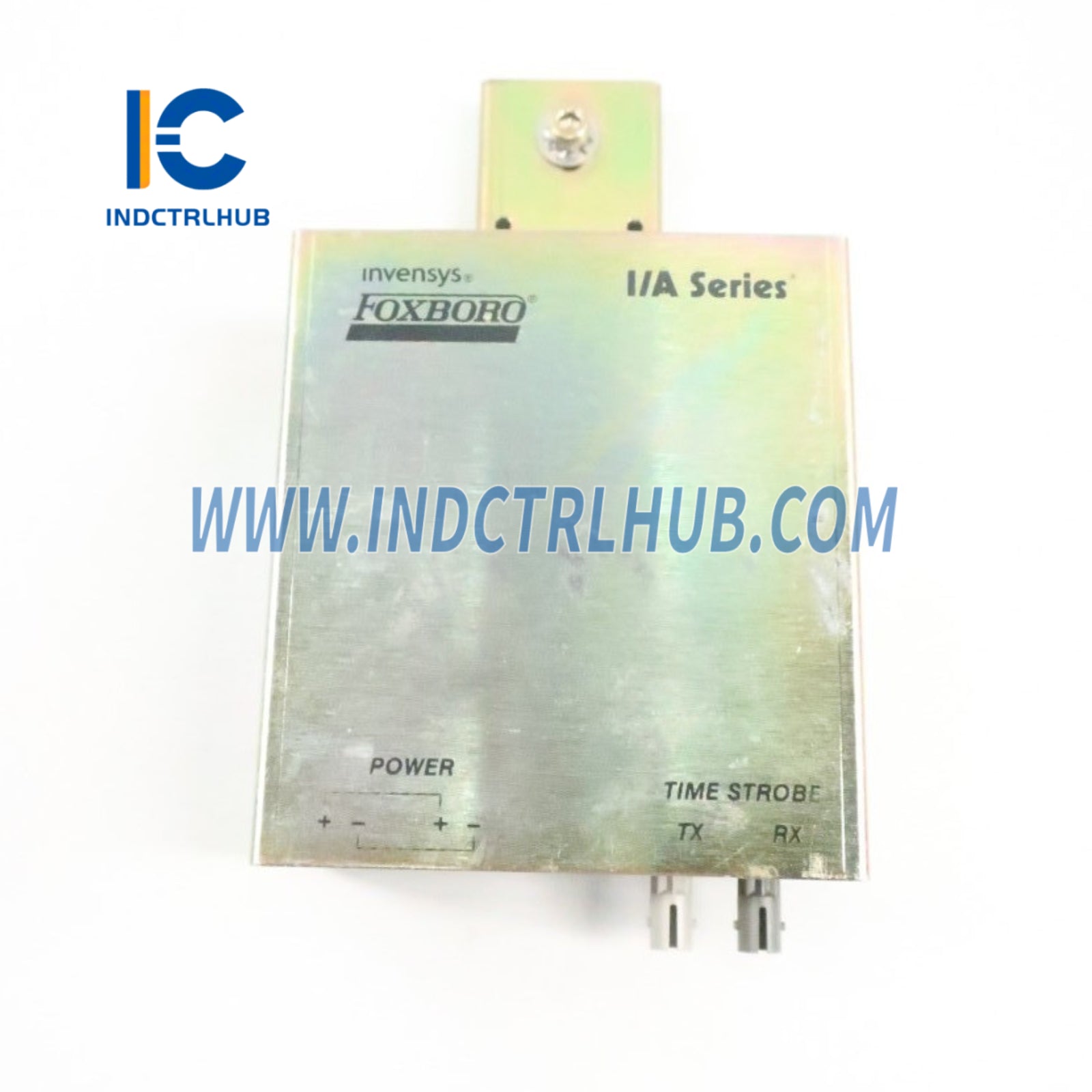
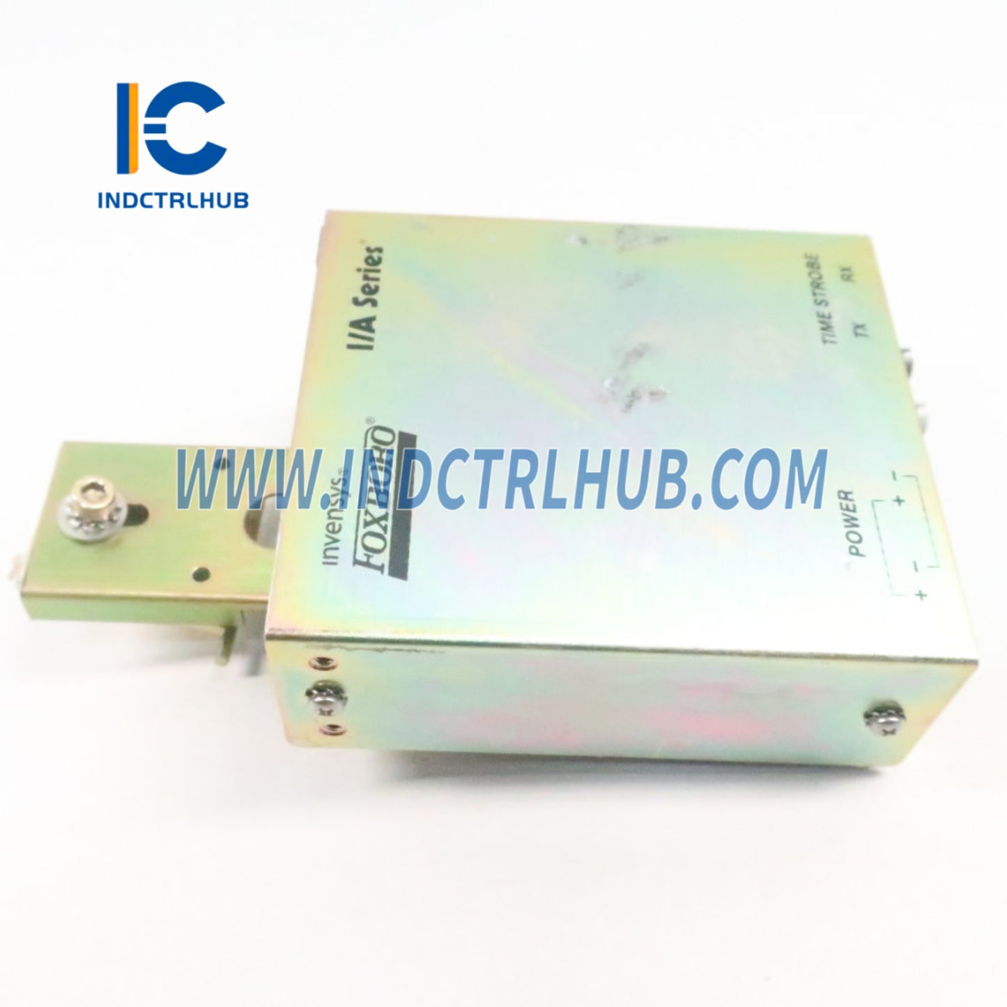
| Product Type | Time Strobe Converter (TSC) with Multi-Mode Fiber (MMF) Input |
| Function | Converts time strobe pulse from MTK station via MMF to eight RS-422 differential output signals for control stations |
| System Compatibility | EcoStruxure Foxboro DCS Process Automation System (FCP280, FCP270, FCM100Et, ZCP270) |
| Associated PSS Document | PSS 41H-4TIMESNC (Time Synchronization Equipment) |
⚙️ Functional Specifications
| Feature | Specification |
|---|---|
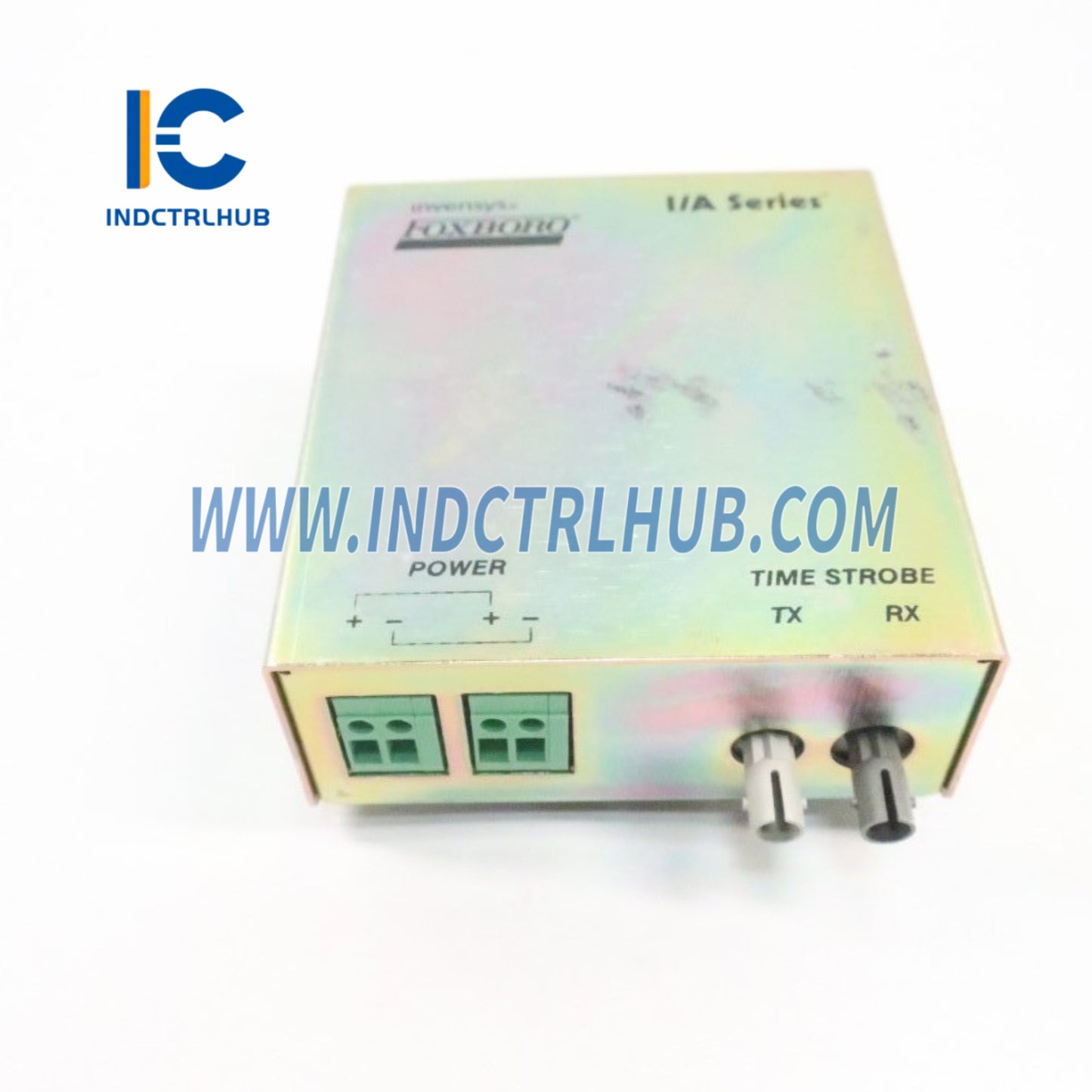
| Inputs | One 62.5/125 micron, simplex multi-mode fiber optic (MMF) input from MTK modem, MMF-compatible Time Strobe Extender (RH100AM), or another TSC |
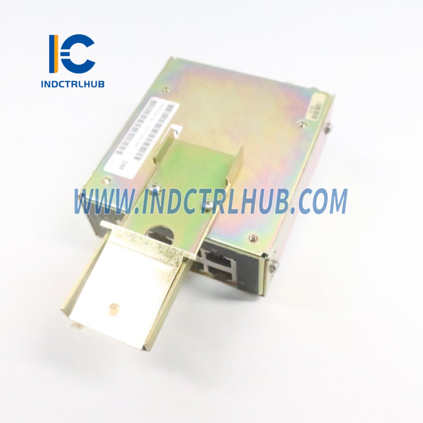
| Outputs | - Electrical Signal: RS-422 differential - Number: 8 outputs - Protection: Helps protect from shock waves |
| Output Ports | One 62.5/125 micron, simplex multi-mode fiber optic (MMF) output for continuation to next MMF-compatible TSC or MMF-compatible Time Strobe Extender |
| Propagation Delay | - TSC: 1 µs per TSC - Fiber Cable: 5 µs per km |
| Cable Lengths | - Input/Output MMF Cable: 3 m to 2 km (10 to 6,562 ft) per segment; customer-supplied for >50 m (160 ft) - Copper Cable to Controller/Baseplates: 0.5 m to 3 m (1.6 ft to 10 ft) within same enclosure |
| Cable Types | - Fiber Optic: 62.5/125 micron MMF, simplex - Copper: Cat 5 STP cable |
| Cable Connectors | - Fiber Optic Input/Output: 2 ST-type connectors (1 input, 1 output) - Copper Strobe Output: 8 RJ-45 connectors |
| Synchronization | - Synchronizes TDR, TDA, SOE, and FBMs to within 1–3 ms time difference (configuration-dependent) - Note: AC SOE points have ~8–20 ms delay due to 50/60 Hz waveform; use DC inputs for 1 ms synchronization |
| Max TSC Interconnections | Up to 50 TSCs can share power supply connections; additional TSCs can be linked for communication |
| Supported Devices | Time strobes connect to FCP280, FCP270, FCM100Et, ZCP270; TDR/TDA and SOE FBMs receive time messages via these devices |
🔋 Power Requirements
| Feature | Specification |
|---|---|
| Input Voltage Range | 21 to 42 V DC |
| Input Power Terminal Blocks | 2 (1 for power input, 1 for power output to next TSC in same enclosure) |
| Power Consumption | - 3.3 W at 24 V DC with all 8 outputs used - 4.1 W at 39 V DC with all 8 outputs used |
📏 Physical Specifications
| Feature | Specification |
|---|---|
| Mounting | - DIN Rail: Supports 32 mm (1.26 in) and 35 mm (1.38 in) styles - Rack: 19-inch rack on specially designed shelf |
| Dimensions (Nominal) | - Height: 38 mm (1.5 in) - Width: 102 mm (4.0 in) - Depth: 89 mm (3.5 in) |
| Weight (Approximate) | 681 g (1.5 lb) |
| Indicators | - Green: Power on - Yellow: Dual-purpose (steady for link, flashing for time pulse signal output) |
| Construction | Rugged design for enclosure mounting, suitable for control station environments |
🌡️ Environmental Specifications
| Parameter | Operating | Storage |
|---|---|---|
| Temperature | 0 to +60°C (32 to +140°F) | -40 to +70°C (-40 to +158°F) |
| Relative Humidity | 5 to 95% (non-condensing) | 5 to 95% (non-condensing) |
| Vibration | 5.0 m/s² (0.5 g) from 5 to 200 Hz | 5.0 m/s² (0.5 g) from 5 to 200 Hz |
| Contamination | Class G1 (Mild) per ISA S71.04 | Class G1 (Mild) per ISA S71.04 |
Note: Environmental limits may be enhanced by enclosure type (see applicable enclosure PSS, e.g., PSS 41H-2GOV).
✅ Regulatory Compliance
| Certification Type | Details |
|---|---|
| Electromagnetic Compatibility (EMC) | - European EMC Directive 2014/30/EU - Meets EN 61326-1:2013 Class A Emissions and Industrial Immunity Levels |
| Product Safety | - UL/UL-C listed for Ordinary Locations and Class I, Groups A-D, Division 2, T4 enclosure-based systems when connected to specified Foxboro DCS processor modules (per B0400FA) - Meets Class 2 requirements per NEC (NFPA No.70) and CEC (CSA C22.1) - European Low Voltage Directive 2014/35/EU - ATEX Directive 2014/34/EU: DEMKO certified Ex nA IIC T4 for Zone 2 enclosures (per B0400FA) |
| RoHS Compliance | Conforms to RoHS Directive 2011/65/EU (RH-prefixed components) |
| California Prop 65 | Contains lead/lead compounds; warning required per www.p65warnings.ca.gov |
🔌 Additional Features
| Feature | Details |
|---|---|
| Installation | Mounts in enclosures with controller stations; supports non-redundant or redundant time strobe networks |
| Redundancy Support | Compatible with redundant MTK systems; can be removed/replaced without affecting other path in redundant setup |
| Enclosure Suitability | Designed for Class G1 mild environments; suitable for control room or field enclosures |
| Daisy-Chaining | MMF output allows connection to additional MMF-compatible TSCs or extenders for plant-wide distribution |
📦 Ordering Information
| Field | Details |
|---|---|
| Part Number | RH972KA (Time Strobe Converter, MMF-compatible) |
| Associated Components | - MTK Modem: RH972SB - Time Strobe Extender: RH100AM (MMF) - GPS Antenna/Receiver: K0204AX, K0204AY, K0204BB - Time Strobe Generator: K0204AZ - GPS Fiber Optic Isolator: P0972VZ (optional) |
| Related PSS Documents | - PSS 41H-4TIMESNC (Time Synchronization Equipment) - PSS 41H-1TIME (Time Synchronization Overview) - B0700AQ (Time Synchronization User’s Guide) - B0400FA (Standard and Compact 200 Series Subsystem User’s Guide) |