
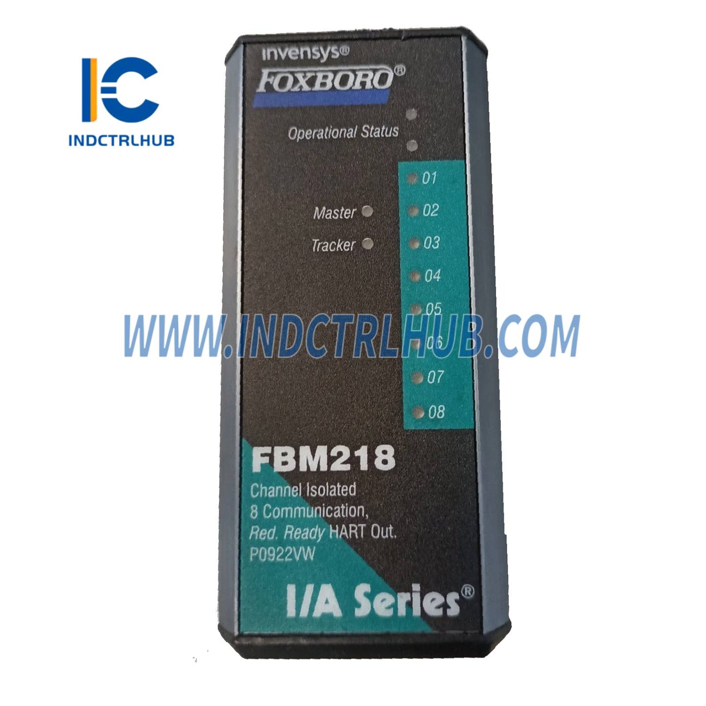
Foxboro P0922VW Communication Redundant Output Module
Foxboro P0922VW Communication Redundant Output Module
Manufacturer: Foxboro
Product No.: P0922VW
Condition:1000 in stock
Product Type: Communication Redundant Output Module
Product Origin: USA
Payment: T/T, Western Union
Weight: 1000g
Shipping port: Xiamen
Warranty: 12 months
- 24/7 Support
- 30-Day Returns
- Fast Shipping
Product Parameters for P0922VW (FBM218 HART Communication Redundant Output Module)
__ Product Overview
| Field | Details |
|---|---|
| Manufacturer | Foxboro (by Schneider Electric) |
| Part Number | P0922VW (superseded by RH922WW) |
| Product Type | FBM218 HART Communication Redundant Output Module |
| Function | Provides eight isolated output channels for 4 to 20 mA analog signals or digital HART signals superimposed on 4 to 20 mA outputs, user-selectable per channel |
| System Compatibility | Foxboro Evo Process Automation System, interfaces with Fieldbus Communication Module (FCM) or Field Control Processor (FCP) |
| Associated PSS Document | PSS 31H-2S218 |
___ Functional Specifications
| Feature | Specification |
|---|---|
| Module Type | HART Communication Redundant Output Module |
| Output Channels | 8 isolated channels, each providing: - Standard 4 to 20 mA analog output - Digital HART FSK signal superimposed on 4 to 20 mA output |
| Redundancy | Module pair (Master and Tracker) provides redundancy at FBM level; outputs wired to one TA via redundant adapter |
| HART Protocol Version | Supports HART Versions 5, 6, or 7 |
| Communication | Point-to-point, master/slave, asynchronous, half-duplex, 1200 baud |
| Error Checking | Parity on each byte, 32-bit CRC on each message |
| Message Speed | 2 messages per second per field device |
| Fastest ECB Block Period | 100 ms (refer to Control Processor Sizing Guidelines for optimal loading) |
| Maximum Distance | Up to 3030 m (10,000 ft), per HART FSK physical layer spec HCF_SPEC-54, Rev 8.1 (decreases with intrinsic safety barriers) |
| Analog Accuracy | ±0.05% of span (4 to 20 mA) |
| Output Load | 750 Ω maximum |
| Maximum Rate of Change | 20 mA in 60 ms |
| Resolution | 13 bits |
| Loop Power Supply | Isolated power supply for each channel, galvanically isolated, current-limited (~25 mA normal, up to 100 mA if output FET shorts), voltage-regulated |
| Isolation | Channels galvanically isolated (optical and transformer) from each other, ground, and module logic; withstands 600 V AC for 1 minute |
| Fieldbus Communication | Communicates via redundant 2 Mbps HDLC Fieldbus (Path A or B) |
| Heat Dissipation | 5 W (maximum) |
__ Power Requirements
| Feature | Specification |
|---|---|
| Input Voltage Range | 24 V DC +5%/-10% (redundant) |
| Power Consumption | 7 W (maximum) |
__ï¸ Environmental Specifications
| Parameter | Specification |
|---|---|
| Operating Temperature | Module and TA (PA): -20 to +70°C (-4 to +158°F) |
| Relative Humidity | 5 to 95% (noncondensing) |
| Operating Altitude | -300 to +3,000 m (-1,000 to +10,000 ft) |
| Storage Temperature | -40 to +70°C (-40 to +158°F) |
| Storage Altitude | -300 to +12,000 m (-1,000 to +40,000 ft) |
| Contamination | Suitable for Class G3 (harsh) environments per ISA S71.04, EIA 364-65 Class III |
| Vibration | 7.5 m/s² (0.75 g) from 5 to 500 Hz |
_ Regulatory Compliance
| Certification Type | Details |
|---|---|
| Electromagnetic Compatibility (EMC) | Meets European EMC Directives 2004/108/EC (pre-Apr 20, 2016) and 2014/30/EU (post-Apr 20, 2016): - EN61326-1:2013 Class A Emissions and Industrial Immunity Levels |
| RoHS Compliance | Complies with European RoHS Directive 2011/65/EU |
| Product Safety (UL) | UL/UL-C listed for Class I, Groups A-D, Division 2, T4 enclosure-based systems; meets Class 2 requirements (NFPA 70, CSA C22.1) when connected to specified processors per Standard and Compact 200 Series Subsystem User__ Guide (B0400FA) |
| ATEX | DEMKO certified Ex nA IIC T4 for Zone 2 enclosure per Directives 94/9/EC (pre-Apr 20, 2016) and 2014/34/EU (post-Apr 20, 2016) when connected per B0400FA |
| Marine Certification | ABS Type Approved and Bureau Veritas Marine certified for Environmental Category EC31 |
| Calibration | No calibration required for module or termination assembly |
__ Physical Specifications
| Feature | Specification |
|---|---|
| Mounting (Module) | Mounts on baseplate (DIN rail or 19-inch rack with mounting kit, per PSS 31H-2SBASPLT); redundant modules in adjacent positions (1-2, 3-4, 5-6, or 7-8) |
| Mounting (TA) | DIN rail (32 mm or 35 mm) |
| Weight (Module) | 284 g (10 oz) approximate |
| Weight (TA) | Compression: 181 g (0.40 lb) approximate |
| Dimensions (Module) | Height: 102 mm (4 in), 114 mm (4.5 in) with lugs Width: 45 mm (1.75 in) Depth: 104 mm (4.11 in) |
| Dimensions (TA) | Refer to page 10 (Compression TA, nominal dimensions not explicitly listed but consistent with series) |
__ Termination Assemblies and Cables
| Feature | Specification |
|---|---|
| TA Part Number | RH926SP (supersedes P0926SP, P0917XV) |
| Termination Type | Compression (Polyamide) |
| TA Cable Type | Type 1 (25-pin male D-subminiature connector) |
| TA Certification | Type 1: UL/UL-C listed for Class I, Groups A-D, Division 2, T4; DEMKO certified Ex nA IIC T4 for Zone 2 Type 2: UL/UL-C and DEMKO certified as associated apparatus for non-incendive field circuits (Class I, Groups A-D, Division 2; Zone 2, Group IIC); Class 2 limited energy (60 V DC, 30 V AC, 100 VA or less) |
| Redundant Adapter | RH916QD (supersedes P0916QD) |
| Cable Lengths | Up to 30 m (98 ft): 0.5 m, 1.0 m, 2.0 m, 3.0 m, 5.0 m, 10.0 m, 15.0 m, 20.0 m, 25.0 m, 30.0 m |
| Cable Materials | Polyurethane (P/PVC) or Low Smoke Zero Halogen (LSZH) |
| Cable Part Numbers | P/PVC: RH916DA, RH916DB, RH931RM, RH916DC, RH916DD, RH916DE, RH916DF, RH916DG, RH916DH, RH916DJ LSZH: RH928AA, RH928AB, RH928AC, RH928AD, RH928AE, RH928AF, RH928AG, RH928AH, RH928AJ, RH928AK |
| Field Wiring (Compression) | Solid/Stranded: 0.2 to 4 mm² / 0.2 to 2.5 mm² (24 to 12 AWG) Stranded with Ferrules: 0.2 to 2.5 mm² |
__ Additional Features
| Feature | Details |
|---|---|
| Redundancy | Master/Tracker pair configuration; outputs combined in series via redundant adapter (RH916QD); failed module outputs 0 mA, healthy module maintains current |
| Fail-Safe Options | Configurable: Fail-Safe Action (Hold/Fallback), Analog Output Fail-Safe Fallback Data (0 mA per channel), Fieldbus Fail-Safe Enable, Fieldbus Fail-Safe Delay Time |
| Physical Design | Rugged extruded aluminum exterior for circuit protection |
| Visual Indicators | LEDs for operational status, channel communication activity, and Master/Tracker status |
| Removal/Replacement | Can be removed/replaced without disconnecting field wiring, power, or comms |
| HART Commands | Supports universal, common practice, and device-specific commands via Intelligent Field Device Configurator (IFDC, PSS 21S-8A2 B3); no burst mode |
| Loop Resistance | Sufficient for HART Hand-Held Terminal or PC20 IFDC (PSS 2A-1Z3 E) |
__ Ordering Information
| Field | Details |
|---|---|
| Part Number | P0922VW (FBM218 Module, superseded by RH922WW) |
| Redundant Adapter | RH916QD (supersedes P0916QD) |
| TA Part Number | RH926SP (supersedes P0926SP, P0917XV) |
| Conditions of Use | Must be installed per Standard and Compact 200 Series Subsystem User__ Guide (B0400FA) |
_
Product Description
Product Parameters for P0922VW (FBM218 HART Communication Redundant Output Module)
__ Product Overview
| Field | Details |
|---|---|
| Manufacturer | Foxboro (by Schneider Electric) |
| Part Number | P0922VW (superseded by RH922WW) |
| Product Type | FBM218 HART Communication Redundant Output Module |
| Function | Provides eight isolated output channels for 4 to 20 mA analog signals or digital HART signals superimposed on 4 to 20 mA outputs, user-selectable per channel |
| System Compatibility | Foxboro Evo Process Automation System, interfaces with Fieldbus Communication Module (FCM) or Field Control Processor (FCP) |
| Associated PSS Document | PSS 31H-2S218 |
___ Functional Specifications
| Feature | Specification |
|---|---|
| Module Type | HART Communication Redundant Output Module |
| Output Channels | 8 isolated channels, each providing: - Standard 4 to 20 mA analog output - Digital HART FSK signal superimposed on 4 to 20 mA output |
| Redundancy | Module pair (Master and Tracker) provides redundancy at FBM level; outputs wired to one TA via redundant adapter |
| HART Protocol Version | Supports HART Versions 5, 6, or 7 |
| Communication | Point-to-point, master/slave, asynchronous, half-duplex, 1200 baud |
| Error Checking | Parity on each byte, 32-bit CRC on each message |
| Message Speed | 2 messages per second per field device |
| Fastest ECB Block Period | 100 ms (refer to Control Processor Sizing Guidelines for optimal loading) |
| Maximum Distance | Up to 3030 m (10,000 ft), per HART FSK physical layer spec HCF_SPEC-54, Rev 8.1 (decreases with intrinsic safety barriers) |
| Analog Accuracy | ±0.05% of span (4 to 20 mA) |
| Output Load | 750 Ω maximum |
| Maximum Rate of Change | 20 mA in 60 ms |
| Resolution | 13 bits |
| Loop Power Supply | Isolated power supply for each channel, galvanically isolated, current-limited (~25 mA normal, up to 100 mA if output FET shorts), voltage-regulated |
| Isolation | Channels galvanically isolated (optical and transformer) from each other, ground, and module logic; withstands 600 V AC for 1 minute |
| Fieldbus Communication | Communicates via redundant 2 Mbps HDLC Fieldbus (Path A or B) |
| Heat Dissipation | 5 W (maximum) |
__ Power Requirements
| Feature | Specification |
|---|---|
| Input Voltage Range | 24 V DC +5%/-10% (redundant) |
| Power Consumption | 7 W (maximum) |
__ï¸ Environmental Specifications
| Parameter | Specification |
|---|---|
| Operating Temperature | Module and TA (PA): -20 to +70°C (-4 to +158°F) |
| Relative Humidity | 5 to 95% (noncondensing) |
| Operating Altitude | -300 to +3,000 m (-1,000 to +10,000 ft) |
| Storage Temperature | -40 to +70°C (-40 to +158°F) |
| Storage Altitude | -300 to +12,000 m (-1,000 to +40,000 ft) |
| Contamination | Suitable for Class G3 (harsh) environments per ISA S71.04, EIA 364-65 Class III |
| Vibration | 7.5 m/s² (0.75 g) from 5 to 500 Hz |
_ Regulatory Compliance
| Certification Type | Details |
|---|---|
| Electromagnetic Compatibility (EMC) | Meets European EMC Directives 2004/108/EC (pre-Apr 20, 2016) and 2014/30/EU (post-Apr 20, 2016): - EN61326-1:2013 Class A Emissions and Industrial Immunity Levels |
| RoHS Compliance | Complies with European RoHS Directive 2011/65/EU |
| Product Safety (UL) | UL/UL-C listed for Class I, Groups A-D, Division 2, T4 enclosure-based systems; meets Class 2 requirements (NFPA 70, CSA C22.1) when connected to specified processors per Standard and Compact 200 Series Subsystem User__ Guide (B0400FA) |
| ATEX | DEMKO certified Ex nA IIC T4 for Zone 2 enclosure per Directives 94/9/EC (pre-Apr 20, 2016) and 2014/34/EU (post-Apr 20, 2016) when connected per B0400FA |
| Marine Certification | ABS Type Approved and Bureau Veritas Marine certified for Environmental Category EC31 |
| Calibration | No calibration required for module or termination assembly |
__ Physical Specifications
| Feature | Specification |
|---|---|
| Mounting (Module) | Mounts on baseplate (DIN rail or 19-inch rack with mounting kit, per PSS 31H-2SBASPLT); redundant modules in adjacent positions (1-2, 3-4, 5-6, or 7-8) |
| Mounting (TA) | DIN rail (32 mm or 35 mm) |
| Weight (Module) | 284 g (10 oz) approximate |
| Weight (TA) | Compression: 181 g (0.40 lb) approximate |
| Dimensions (Module) | Height: 102 mm (4 in), 114 mm (4.5 in) with lugs Width: 45 mm (1.75 in) Depth: 104 mm (4.11 in) |
| Dimensions (TA) | Refer to page 10 (Compression TA, nominal dimensions not explicitly listed but consistent with series) |
__ Termination Assemblies and Cables
| Feature | Specification |
|---|---|
| TA Part Number | RH926SP (supersedes P0926SP, P0917XV) |
| Termination Type | Compression (Polyamide) |
| TA Cable Type | Type 1 (25-pin male D-subminiature connector) |
| TA Certification | Type 1: UL/UL-C listed for Class I, Groups A-D, Division 2, T4; DEMKO certified Ex nA IIC T4 for Zone 2 Type 2: UL/UL-C and DEMKO certified as associated apparatus for non-incendive field circuits (Class I, Groups A-D, Division 2; Zone 2, Group IIC); Class 2 limited energy (60 V DC, 30 V AC, 100 VA or less) |
| Redundant Adapter | RH916QD (supersedes P0916QD) |
| Cable Lengths | Up to 30 m (98 ft): 0.5 m, 1.0 m, 2.0 m, 3.0 m, 5.0 m, 10.0 m, 15.0 m, 20.0 m, 25.0 m, 30.0 m |
| Cable Materials | Polyurethane (P/PVC) or Low Smoke Zero Halogen (LSZH) |
| Cable Part Numbers | P/PVC: RH916DA, RH916DB, RH931RM, RH916DC, RH916DD, RH916DE, RH916DF, RH916DG, RH916DH, RH916DJ LSZH: RH928AA, RH928AB, RH928AC, RH928AD, RH928AE, RH928AF, RH928AG, RH928AH, RH928AJ, RH928AK |
| Field Wiring (Compression) | Solid/Stranded: 0.2 to 4 mm² / 0.2 to 2.5 mm² (24 to 12 AWG) Stranded with Ferrules: 0.2 to 2.5 mm² |
__ Additional Features
| Feature | Details |
|---|---|
| Redundancy | Master/Tracker pair configuration; outputs combined in series via redundant adapter (RH916QD); failed module outputs 0 mA, healthy module maintains current |
| Fail-Safe Options | Configurable: Fail-Safe Action (Hold/Fallback), Analog Output Fail-Safe Fallback Data (0 mA per channel), Fieldbus Fail-Safe Enable, Fieldbus Fail-Safe Delay Time |
| Physical Design | Rugged extruded aluminum exterior for circuit protection |
| Visual Indicators | LEDs for operational status, channel communication activity, and Master/Tracker status |
| Removal/Replacement | Can be removed/replaced without disconnecting field wiring, power, or comms |
| HART Commands | Supports universal, common practice, and device-specific commands via Intelligent Field Device Configurator (IFDC, PSS 21S-8A2 B3); no burst mode |
| Loop Resistance | Sufficient for HART Hand-Held Terminal or PC20 IFDC (PSS 2A-1Z3 E) |
__ Ordering Information
| Field | Details |
|---|---|
| Part Number | P0922VW (FBM218 Module, superseded by RH922WW) |
| Redundant Adapter | RH916QD (supersedes P0916QD) |
| TA Part Number | RH926SP (supersedes P0926SP, P0917XV) |
| Conditions of Use | Must be installed per Standard and Compact 200 Series Subsystem User__ Guide (B0400FA) |
_