


Product Description
Product Parameters for P0922VV (FBM216 HART Communication Redundant Input Interface Module)
📘 Product Overview
| Field | Details |
|---|---|
| Manufacturer | Foxboro (by Invensys Process Systems) |
| Part Number | P0922VV |
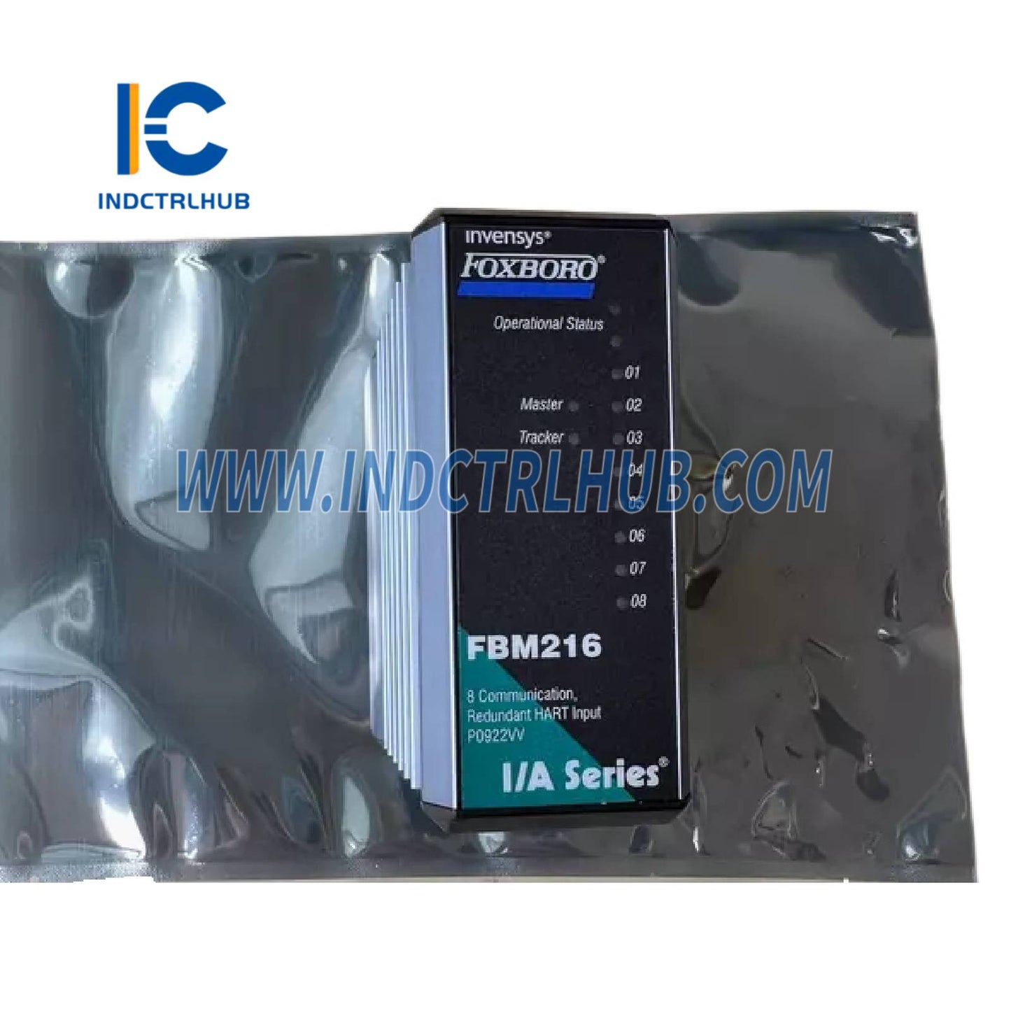
| Product Type | FBM216 HART Communication Redundant Input Interface Module |
| Function | Provides eight redundant input channels for 4 to 20 mA analog signals or digital HART signals superimposed on 4 to 20 mA analog inputs |
| System Compatibility | I/A Series System, interfaces with Fieldbus Communication Module (FCM) or Field Control Processor (FCP) |
| Associated PSS Document | PSS 21H-2Z16 B4 |
⚙️ Functional Specifications
| Feature | Specification |
|---|---|
| Module Type | HART Communication Redundant Input Interface Module |
| Input Channels | 8 group-isolated channels, each accepting: - Standard 4 to 20 mA analog signal - Digital HART FSK signal superimposed on 4 to 20 mA |
| Redundancy | Module pair (Master and Tracker) provides redundancy at FBM level; single TA used for field inputs |
| HART Protocol Version | HART Protocol v6 |
| Communication | Point-to-point, master/slave, asynchronous, half-duplex, 1200 baud |
| Message Speed | 2 messages per second per field device |
| Fastest ECB Block Period | 500 ms |
| Maximum Distance | Up to 3030 m (10,000 ft), per HART FSK physical layer spec HCF_SPEC-54, Rev 8.1 (decreases with intrinsic safety barriers) |
| Compliance Voltage | 18 V DC minimum at 20.5 mA |
| Sense Resistor | 61.9 Ω nominal |
| Total Input Resistance | 280 Ω minimum |
| Analog Accuracy | ±0.075% of full scale (with Rev G FBM216 and Rev C Redundancy Adapter); earlier revisions (A-F with Adapter A-B) have ±0.3% (external power) or ±0.6% (internal power) |
| Temperature Coefficient | 50 ppm/°C |
| Resolution | 15 bits |
| Update Rate | 100 ms |
| Integration Time | 500 ms |
| Common Mode Rejection | >100 dB at 50 or 60 Hz |
| Normal Mode Rejection | >35 dB at 50 or 60 Hz |
| Maximum Loop Resistance | 280 Ω (not including field device) |
| Loop Power Supply | 24 V DC ±10% common power supply for all channels (internal); optional external power supply (requires Cable Balun Module for 2+ channels) |
| Loop Power Protection | Galvanically group-isolated, current-limited (<30 mA single module, <60 mA redundant modules, up to 85 mA if shorted), voltage-regulated |
| Input Impedance | 280 Ω minimum |
| Isolation | Channels not isolated from each other but galvanically isolated (optical and transformer) as a group from ground and module logic; withstands 600 V AC for 1 minute |
| Fieldbus Communication | Communicates via redundant 2 Mbps module Fieldbus (Path A or B) |
| Heat Dissipation | 4 W (maximum) |
🔌 Power Requirements
| Feature | Specification |
|---|---|
| Input Voltage Range | 24 V DC ±5% (redundant) |
| Power Consumption | 7 W (maximum) |
🌡️ Environmental Specifications
| Parameter | Specification |
|---|---|
| Operating Temperature | Module: -20 to +70°C (-4 to +158°F) Termination Assembly (PVC): -20 to +50°C (-4 to +122°F) Termination Assembly (PA): -20 to +70°C (-4 to +158°F) |
| Relative Humidity | 5 to 95% (noncondensing) |
| Operating Altitude | -300 to +3,000 m (-1,000 to +10,000 ft) |
| Storage Temperature | -40 to +70°C (-40 to +158°F) |
| Storage Altitude | -300 to +12,000 m (-1,000 to +40,000 ft) |
| Contamination | Suitable for Class G3 (harsh) environments per ISA S71.04, EIA 364-65 Class III |
| Vibration | 7.5 m/s² (0.75 g) from 5 to 500 Hz |
✅ Regulatory Compliance
| Certification Type | Details |
|---|---|
| Electromagnetic Compatibility (EMC) | Meets European EMC Directive 89/336/EEC: - EN 50081-2 (Emission) - EN 50082-2 (Immunity) - EN 61326 Annex A (Industrial Levels) - CISPR 11 Class A - IEC 61000-4-2 (ESD: 4 kV contact, 8 kV air) - IEC 61000-4-3 (Radiated: 10 V/m, 80-1000 MHz) - IEC 61000-4-4 (EFT: 2 kV on I/O, power, comms) - IEC 61000-4-5 (Surge: 2 kV power, 1 kV I/O, comms) - IEC 61000-4-6 (Conducted: 10 V, 150 kHz-80 MHz) - IEC 61000-4-8 (Magnetic: 30 A/m, 50/60 Hz) |
| Product Safety (UL) | UL/UL-C listed for Class I, Groups A-D, Division 2, T4 enclosure-based systems; listed as associated apparatus for non-incendive circuits in hazardous locations per I/A Series User’s Guide (B0400FA); meets Class 2 requirements (NFPA 70, CSA C22.1) when powered by FBM |
| ATEX (CENELEC) | Certified EEx nA IIC T4 for Zone 2 enclosure; certified as associated apparatus for non-incendive field circuits in Zone 2, Group IIC per I/A Series User’s Guide (B0400FA); complies with Low Voltage Directive 73/23/EEC and ATEX Directive 94/9/EC |
| Calibration | No calibration required for module or termination assembly |
📏 Physical Specifications
| Feature | Specification |
|---|---|
| Mounting (Module) | Mounts on modular baseplate (DIN rail or 19-inch rack with mounting kit, per PSS 21H-2W6 B4); redundant modules in adjacent positions (1-2, 3-4, 5-6, or 7-8) |
| Mounting (TA) | DIN rail (32 mm or 35 mm) |
| Mass (Module) | 284 g (10 oz) approximate |
| Mass (TA) | Compression: 181 g (0.40 lb) approximate Ring Lug: 249 g (0.55 lb) approximate |
| Dimensions (Module) | Height: 102 mm (4 in), 114 mm (4.5 in) with lugs Width: 45 mm (1.75 in) Depth: 104 mm (4.11 in) |
| Dimensions (TA) | Compression/Ring Lug: Refer to page 11 (dimensions not explicitly listed but consistent with FBM214) |
🔗 Termination Assemblies and Cables
| Feature | Specification |
|---|---|
| TA Part Numbers | PVC: P0916BX (Compression), P0926EA (Ring Lug) PA: P0926TD (Compression) |
| Termination Type | Compression (PVC/PA) or Ring Lug (PVC) |
| TA Cable Type | Type 1 (25-pin male D-subminiature connector) |
| TA Certification | Type 1: UL/UL-C listed for Class I, Groups A-D, Division 2, T4; CENELEC EEx nA IIC T4 for Zone 2 Type 2: UL/UL-C and CENELEC certified as associated apparatus for non-incendive field circuits |
| Redundant Adapter | P0917XQ (connects redundant module pair to single TA) |
| Cable Lengths | Up to 30 m (98 ft): 0.5 m, 1.0 m, 2.0 m, 3.0 m, 5.0 m, 10.0 m, 15.0 m, 20.0 m, 25.0 m, 30.0 m |
| Cable Materials | Polyurethane (P/PVC) or Hypalon/XLPE (H/XLPE) |
| Cable Part Numbers | P/PVC: P0916DA, P0916DB, P0931RM, P0916DC, P0916DD, P0916DE, P0916DF, P0916DG, P0916DH, P0916DJ H/XLPE: P0916VA, P0916VB, P0931RR, P0916VC, P0916VD, P0916VE, P0916VF, P0916VG, P0916VH, P0916VJ |
| Field Wiring (Compression) | Solid/Stranded: 0.2 to 4 mm² / 0.2 to 2.5 mm² (24 to 12 AWG) Stranded with Ferrules: 0.2 to 2.5 mm² |
| Field Wiring (Ring Lug) | #6 connectors (9.5 mm), 0.5 to 4 mm² (22 to 12 AWG) |
🔧 Additional Features
| Feature | Details |
|---|---|
| Redundancy | Master/Tracker pair configuration; field inputs wired to one TA via redundant adapter (P0917XQ); diode OR’d power ensures continuous operation |
| Compact Design | Rugged extruded aluminum exterior for circuit protection |
| Visual Indicators | LEDs for operational status, redundancy status (Master/Tracker), and channel communication activity |
| Removal/Replacement | Can be removed/replaced without disconnecting field wiring, power, or comms; replacement does not disrupt other module |
| Cable Balun Module | Required for external power supply with 2+ channels to prevent crosstalk |
| HART Commands | Supports universal, common practice, and device-specific commands via Intelligent Field Device Configurator (IFDC, PSS 21S-8A2 B3); no burst mode |
| Sigma-Delta Conversion | High-accuracy analog-to-digital conversion for each channel |
📦 Ordering Information
| Field | Details |
|---|---|
| Part Number | P0922VV (FBM216 Module) |
| Redundant Adapter | P0917XQ |
| TA Part Numbers | P0916BX, P0926EA, P0926TD (see Termination Assemblies section) |
| Conditions of Use | Must be installed per I/A Series DIN Rail Mounted Subsystem User’s Guide (B0400FA) |