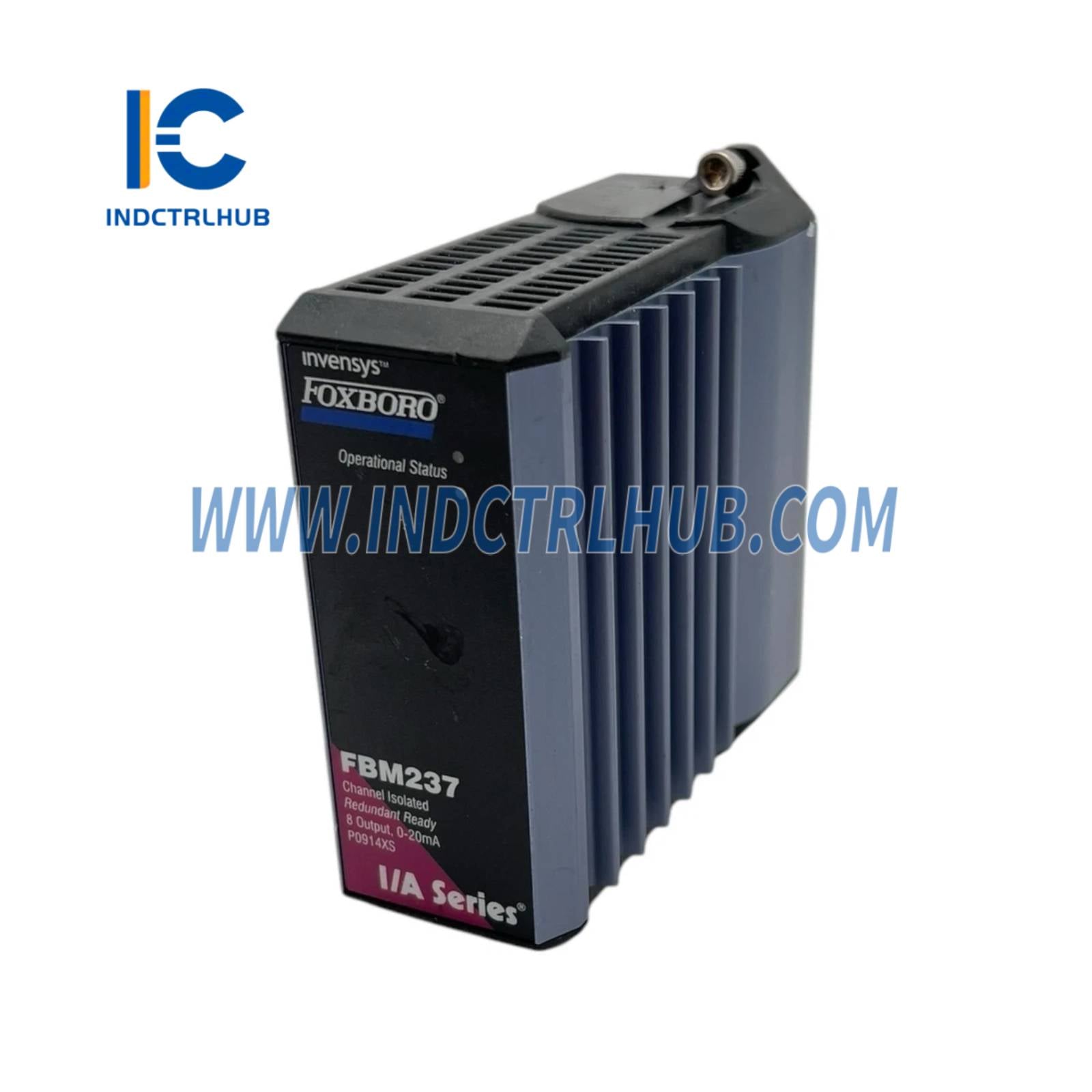
Foxboro P0914XS 0 to 20 mA Output Module
Foxboro P0914XS 0 to 20 mA Output Module
Manufacturer: Foxboro
Product No.: P0914XS
Condition:1000 in stock
Product Type: 0 to 20 mA Output Module
Product Origin: USA
Payment: T/T, Western Union
Weight: 181g
Shipping port: Xiamen
Warranty: 12 months
- 24/7 Support
- 30-Day Returns
- Fast Shipping
Product Parameters for FBM237 P0914XS
__ Product Overview
| Field | Details |
|---|---|
| Manufacturer | Foxboro (by Schneider Electric) |
| Model Number | FBM237 (Part Number: P0914XS) |
| Product Type | 0 to 20 mA Output Module (Redundant Ready) |
| Function | Eight 0-20 mA analog output channels, compatible with HART field devices |
| System Compatibility | Interfaces with Foxboro Evo DCS via redundant 2 Mbps module Fieldbus; compatible with Standard 200 Series baseplates |
| Included Components | FBM237 module; requires separate Termination Assembly (TA), termination cables, and redundant adapter (for redundant configurations) |
| Redundancy | Supports redundant pair operation with common TA; uses AOUTR function block for redundant output management |
___ Hardware Specifications
| Feature | Specification |
|---|---|
| Output Channels | 8 galvanically isolated channels (non-isolated between redundant pairs) |
| Output Signal | 0 to 20.4 mA dc |
| Accuracy (Includes Linearity) | ±0.05% of span (between 0.1 mA and 20 mA) |
| Accuracy Temperature Coefficient | ±50 ppm/°C |
| Output Load | 750 Ω maximum |
| Output Processing Delay | 30 ms maximum |
| Resolution | 13 bits |
| Loop Power Supply Protection | Current limited (~25 mA per channel); galvanically isolated, voltage regulated |
| Isolation | Each channel galvanically isolated from other channels and ground; withstands 600 V AC for 1 minute (not for permanent connection) |
| Visual Indicators | LEDs for fieldbus module functions and status |
| Construction | Rugged extruded aluminum exterior |
| Weight (Module) | 284 g (10 oz) approximate |
| Dimensions (Module) | 102 mm (4 in) height (114 mm with lugs), 45 mm (1.75 in) width, 104 mm (4.11 in) depth |
__ Power Requirements
| Feature | Specification |
|---|---|
| Input Voltage Range (Redundant) | 24 V DC +5%, -10% |
| Consumption (Maximum) | 7 W at 24 V DC |
| Heat Dissipation (Maximum) | 5 W at 24 V DC |
__ï¸ Environmental Specifications
| Parameter | Specification |
|---|---|
| Operating Temperature (Module) | -20 to +70°C (-4 to +158°F) |
| Operating Temperature (TA, PVC) | -20 to +50°C (-4 to +122°F) |
| Operating Temperature (TA, PA) | -20 to +70°C (-4 to +158°F) |
| Storage Temperature | -40 to +70°C (-40 to +158°F) |
| Relative Humidity | 5 to 95% (non-condensing) |
| Altitude (Operating) | -300 to +3,000 m (-1,000 to +10,000 ft) |
| Altitude (Storage) | -300 to +12,000 m (-1,000 to +40,000 ft) |
| Contamination | Class G3 (harsh) per ISA S71.04, tested per EIA 364-65, Class III |
| Vibration | 7.5 m/s² (0.75 g) from 5 to 500 Hz |
_ Regulatory Compliance
| Standard | Details |
|---|---|
| Electromagnetic Compatibility (EMC) | European EMC Directive 89/336/EEC; EN 50081-2, EN 50082-2, EN 61326 Annex A (Industrial Levels), CISPR 11 Class A; IEC 61000-4-2 (ESD: 4 kV contact, 8 kV air), IEC 61000-4-3 (10 V/m, 80-1000 MHz), IEC 61000-4-4 (2 kV on I/O, power, comms), IEC 61000-4-5 (2 kV power, 1 kV I/O, comms), IEC 61000-4-6 (10 V rms, 150 kHz-80 MHz), IEC 61000-4-8 (30 A/m, 50/60 Hz) |
| Product Safety (UL) | UL/UL-C listed for Class I, Groups A-D, Division 2, T4; Class 2 per NEC (NFPA No.70) and CSA C22.1; associated apparatus for non-incendive circuits per B0400FA |
| Product Safety (Europe) | European Low Voltage Directive 73/23/EEC; ATEX 94/9/EC; CENELEC (DEMKO) EEx nA IIC T4 for Zone 2; associated apparatus for Zone 2, Group IIC per B0400FA |
| Hazardous Location Compliance | Complies with UL, DEMKO, and ATEX for installation per B0400FA |
__ï¸ Installation & Configuration
| Feature | Details |
|---|---|
| Mounting (Module) | Mounts on Standard 200 Series modular baseplate (DIN rail or 19-inch rack with kit); supports up to 8 FBMs; redundant pairs in adjacent odd/even positions (1-2, 3-4, 5-6, 7-8) |
| Mounting (TA) | DIN rail (32 mm or 35 mm) |
| Redundant Configuration | Uses redundant adapter (P0916QD) for single TA connection; AOUTR block manages redundant outputs |
| Fieldbus Communication | Redundant 2 Mbps Fieldbus with FCM or FCP; auto-switches to active path |
| Configurable Options | Fail-Safe Action (Hold/Fallback), Analog Output Fail-Safe Fallback Data (0 mA per channel), Fieldbus Fail-Safe Enable, Fieldbus Fail-Safe Delay Time |
| Calibration | Not required |
| Removal/Replacement | Can be removed/replaced without disconnecting field wiring, power, or communication cables; redundant module replacement does not upset outputs |
__ Termination Assemblies and Cables
| Feature | Specification |
|---|---|
| TA Types | Compression (PVC: P0916QC/P0917QZ, PA: P0916YE), Ring Lug (PVC: P0916QC) |
| TA Part Numbers | P0916QC (PVC, Compression/Ring Lug), P0916YE (PA, Compression), P0917QZ (PVC, Compression with bypass jacks) |
| TA Certification | Type 1: UL/UL-C Class I, Div 2, T4; CENELEC EEx nA IIC T4 (Zone 2); Type 2: Associated apparatus for non-incendive circuits; Type 4/5: Class 2 limited energy or non-hazardous (P0917QZ) |
| TA Wiring (Compression) | Solid/Stranded: 0.2 to 4 mm² / 0.2 to 2.5 mm² (24 to 12 AWG); Ferrules: 0.2 to 2.5 mm² |
| TA Wiring (Ring Lug) | #6 connectors (0.375 in); 0.5 to 4 mm² (22 to 12 AWG) |
| TA Weight (Compression) | 181 g (0.40 lb) approximate |
| TA Weight (Ring Lug) | 249 g (0.55 lb) approximate |
| TA Dimensions (Compression) | 125 mm (4.92 in) height, 76 mm (2.99 in) or 72 mm (2.83 in) depth |
| Cable Types | P/PVC (Polyurethane/PVC, -20 to +80°C), LSZH (Low Smoke Zero Halogen, -40 to +105°C) |
| Cable Lengths | Up to 30 m (98 ft) |
| Cable Connector | 25-pin male D-subminiature |
| Cable Part Numbers (P/PVC) | 0.5 m: P0916DA; 3.0 m: P0916DC; 30 m: P0916DJ (see Table 3 for full list) |
| Cable Part Numbers (LSZH) | 0.5 m: P0928AA; 3.0 m: P0928AD; 30 m: P0928AK (see Table 3 for full list) |
| Redundant Adapter | P0916QD (required for redundant pair to connect to single TA) |
__ Functional Specifications
| Feature | Details |
|---|---|
| Output Range | 0 to 20.4 mA dc per channel |
| HART Protocol Compatibility | Meets impedance requirements for HART high impedance device; supports HART signals without interference |
| Field Device Cabling Distance | Dependent on compliance voltage (18 V DC at 20.4 mA), wire gauge, and field device voltage drop |
| Redundant Operation | AOUTR block sends identical writes to both modules; faulty module outputs 0 mA, healthy module maintains output; diode OR__ power in redundant adapter |
| Fail-Safe Behavior | Configurable Fail-Safe Action (Hold/Fallback); Analog Output Fail-Safe Fallback set to 0 mA per channel |
| Communication | Via redundant 2 Mbps module Fieldbus with FCM or FCP |
__ Ordering Information
| Field | Details |
|---|---|
| Grade | Industrial |
| Model Number | FBM237 (P0914XS) |
| TA Part Numbers | P0916QC (PVC, Compression/Ring Lug), P0916YE (PA, Compression), P0917QZ (PVC, Compression with bypass jacks) |
| Redundant Adapter | P0916QD (for redundant configurations) |
| Cable Part Numbers | P/PVC: P0916DA to P0916DJ; LSZH: P0928AA to P0928AK (see Table 3) |
| Includes | FBM237 module (TA, cables, and redundant adapter ordered separately) |

Product Description
Product Parameters for FBM237 P0914XS
__ Product Overview
| Field | Details |
|---|---|
| Manufacturer | Foxboro (by Schneider Electric) |
| Model Number | FBM237 (Part Number: P0914XS) |
| Product Type | 0 to 20 mA Output Module (Redundant Ready) |
| Function | Eight 0-20 mA analog output channels, compatible with HART field devices |
| System Compatibility | Interfaces with Foxboro Evo DCS via redundant 2 Mbps module Fieldbus; compatible with Standard 200 Series baseplates |
| Included Components | FBM237 module; requires separate Termination Assembly (TA), termination cables, and redundant adapter (for redundant configurations) |
| Redundancy | Supports redundant pair operation with common TA; uses AOUTR function block for redundant output management |
___ Hardware Specifications
| Feature | Specification |
|---|---|
| Output Channels | 8 galvanically isolated channels (non-isolated between redundant pairs) |
| Output Signal | 0 to 20.4 mA dc |
| Accuracy (Includes Linearity) | ±0.05% of span (between 0.1 mA and 20 mA) |
| Accuracy Temperature Coefficient | ±50 ppm/°C |
| Output Load | 750 Ω maximum |
| Output Processing Delay | 30 ms maximum |
| Resolution | 13 bits |
| Loop Power Supply Protection | Current limited (~25 mA per channel); galvanically isolated, voltage regulated |
| Isolation | Each channel galvanically isolated from other channels and ground; withstands 600 V AC for 1 minute (not for permanent connection) |
| Visual Indicators | LEDs for fieldbus module functions and status |
| Construction | Rugged extruded aluminum exterior |
| Weight (Module) | 284 g (10 oz) approximate |
| Dimensions (Module) | 102 mm (4 in) height (114 mm with lugs), 45 mm (1.75 in) width, 104 mm (4.11 in) depth |
__ Power Requirements
| Feature | Specification |
|---|---|
| Input Voltage Range (Redundant) | 24 V DC +5%, -10% |
| Consumption (Maximum) | 7 W at 24 V DC |
| Heat Dissipation (Maximum) | 5 W at 24 V DC |
__ï¸ Environmental Specifications
| Parameter | Specification |
|---|---|
| Operating Temperature (Module) | -20 to +70°C (-4 to +158°F) |
| Operating Temperature (TA, PVC) | -20 to +50°C (-4 to +122°F) |
| Operating Temperature (TA, PA) | -20 to +70°C (-4 to +158°F) |
| Storage Temperature | -40 to +70°C (-40 to +158°F) |
| Relative Humidity | 5 to 95% (non-condensing) |
| Altitude (Operating) | -300 to +3,000 m (-1,000 to +10,000 ft) |
| Altitude (Storage) | -300 to +12,000 m (-1,000 to +40,000 ft) |
| Contamination | Class G3 (harsh) per ISA S71.04, tested per EIA 364-65, Class III |
| Vibration | 7.5 m/s² (0.75 g) from 5 to 500 Hz |
_ Regulatory Compliance
| Standard | Details |
|---|---|
| Electromagnetic Compatibility (EMC) | European EMC Directive 89/336/EEC; EN 50081-2, EN 50082-2, EN 61326 Annex A (Industrial Levels), CISPR 11 Class A; IEC 61000-4-2 (ESD: 4 kV contact, 8 kV air), IEC 61000-4-3 (10 V/m, 80-1000 MHz), IEC 61000-4-4 (2 kV on I/O, power, comms), IEC 61000-4-5 (2 kV power, 1 kV I/O, comms), IEC 61000-4-6 (10 V rms, 150 kHz-80 MHz), IEC 61000-4-8 (30 A/m, 50/60 Hz) |
| Product Safety (UL) | UL/UL-C listed for Class I, Groups A-D, Division 2, T4; Class 2 per NEC (NFPA No.70) and CSA C22.1; associated apparatus for non-incendive circuits per B0400FA |
| Product Safety (Europe) | European Low Voltage Directive 73/23/EEC; ATEX 94/9/EC; CENELEC (DEMKO) EEx nA IIC T4 for Zone 2; associated apparatus for Zone 2, Group IIC per B0400FA |
| Hazardous Location Compliance | Complies with UL, DEMKO, and ATEX for installation per B0400FA |
__ï¸ Installation & Configuration
| Feature | Details |
|---|---|
| Mounting (Module) | Mounts on Standard 200 Series modular baseplate (DIN rail or 19-inch rack with kit); supports up to 8 FBMs; redundant pairs in adjacent odd/even positions (1-2, 3-4, 5-6, 7-8) |
| Mounting (TA) | DIN rail (32 mm or 35 mm) |
| Redundant Configuration | Uses redundant adapter (P0916QD) for single TA connection; AOUTR block manages redundant outputs |
| Fieldbus Communication | Redundant 2 Mbps Fieldbus with FCM or FCP; auto-switches to active path |
| Configurable Options | Fail-Safe Action (Hold/Fallback), Analog Output Fail-Safe Fallback Data (0 mA per channel), Fieldbus Fail-Safe Enable, Fieldbus Fail-Safe Delay Time |
| Calibration | Not required |
| Removal/Replacement | Can be removed/replaced without disconnecting field wiring, power, or communication cables; redundant module replacement does not upset outputs |
__ Termination Assemblies and Cables
| Feature | Specification |
|---|---|
| TA Types | Compression (PVC: P0916QC/P0917QZ, PA: P0916YE), Ring Lug (PVC: P0916QC) |
| TA Part Numbers | P0916QC (PVC, Compression/Ring Lug), P0916YE (PA, Compression), P0917QZ (PVC, Compression with bypass jacks) |
| TA Certification | Type 1: UL/UL-C Class I, Div 2, T4; CENELEC EEx nA IIC T4 (Zone 2); Type 2: Associated apparatus for non-incendive circuits; Type 4/5: Class 2 limited energy or non-hazardous (P0917QZ) |
| TA Wiring (Compression) | Solid/Stranded: 0.2 to 4 mm² / 0.2 to 2.5 mm² (24 to 12 AWG); Ferrules: 0.2 to 2.5 mm² |
| TA Wiring (Ring Lug) | #6 connectors (0.375 in); 0.5 to 4 mm² (22 to 12 AWG) |
| TA Weight (Compression) | 181 g (0.40 lb) approximate |
| TA Weight (Ring Lug) | 249 g (0.55 lb) approximate |
| TA Dimensions (Compression) | 125 mm (4.92 in) height, 76 mm (2.99 in) or 72 mm (2.83 in) depth |
| Cable Types | P/PVC (Polyurethane/PVC, -20 to +80°C), LSZH (Low Smoke Zero Halogen, -40 to +105°C) |
| Cable Lengths | Up to 30 m (98 ft) |
| Cable Connector | 25-pin male D-subminiature |
| Cable Part Numbers (P/PVC) | 0.5 m: P0916DA; 3.0 m: P0916DC; 30 m: P0916DJ (see Table 3 for full list) |
| Cable Part Numbers (LSZH) | 0.5 m: P0928AA; 3.0 m: P0928AD; 30 m: P0928AK (see Table 3 for full list) |
| Redundant Adapter | P0916QD (required for redundant pair to connect to single TA) |
__ Functional Specifications
| Feature | Details |
|---|---|
| Output Range | 0 to 20.4 mA dc per channel |
| HART Protocol Compatibility | Meets impedance requirements for HART high impedance device; supports HART signals without interference |
| Field Device Cabling Distance | Dependent on compliance voltage (18 V DC at 20.4 mA), wire gauge, and field device voltage drop |
| Redundant Operation | AOUTR block sends identical writes to both modules; faulty module outputs 0 mA, healthy module maintains output; diode OR__ power in redundant adapter |
| Fail-Safe Behavior | Configurable Fail-Safe Action (Hold/Fallback); Analog Output Fail-Safe Fallback set to 0 mA per channel |
| Communication | Via redundant 2 Mbps module Fieldbus with FCM or FCP |
__ Ordering Information
| Field | Details |
|---|---|
| Grade | Industrial |
| Model Number | FBM237 (P0914XS) |
| TA Part Numbers | P0916QC (PVC, Compression/Ring Lug), P0916YE (PA, Compression), P0917QZ (PVC, Compression with bypass jacks) |
| Redundant Adapter | P0916QD (for redundant configurations) |
| Cable Part Numbers | P/PVC: P0916DA to P0916DJ; LSZH: P0928AA to P0928AK (see Table 3) |
| Includes | FBM237 module (TA, cables, and redundant adapter ordered separately) |