
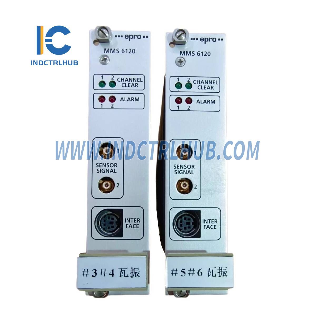
EPRO MMS 6120 Dual Channel Bearing Vibration Monitor
EPRO MMS 6120 Dual Channel Bearing Vibration Monitor
Manufacturer: EPRO
Product No.: MMS 6120
Condition:1000 in stock
Product Type: Dual Channel Bearing Vibration Monitor
Product Origin: USA
Payment: T/T, Western Union
Weight: 1000g
Shipping port: Xiamen
Warranty: 12 months
- 24/7 Support
- 30-Day Returns
- Fast Shipping
Product Overview
The_Emerson MMS 6120_is a_Dual Channel Bearing Vibration Monitor, designed for monitoring vibration levels in rotating machinery using electrodynamic vibration velocity sensors. It features_dual independent sensor inputs,_configurable frequency ranges, and_advanced alarm control_for precise vibration analysis and fault detection.
Key Features
__Two independent inputs for electrodynamic vibration velocity sensors
__Configurable frequency ranges (5 Hz to 1000/1600 Hz)
__Galvanically separated sensor power supply
__Adjustable measuring ranges (5_100 mm/s velocity, 25_1500 µm displacement)
__Redundant power supply input with low power consumption (max. 6W)
__RS-485 bus communication (supports up to 31 modules / 62 channels)
__Wide environmental tolerance (Operating: 0°C to +65°C, Storage: -30°C to +85°C)
Technical Specifications
Sensor Inputs
|
Parameter |
Specification |
|---|---|
|
Input Type |
Two independent electrodynamic vibration velocity sensor inputs (differential type) |
|
Input Resistance |
>100 kΩ |
|
Input Voltage Range |
-5 to +15 V DC |
|
Frequency Ranges |
Selectable from 5/10_50_1000/1600 Hz (DIN 45666 / ISO 3945) |
|
Lifting Coil Current |
Buffered lifting coil current output (open and short circuit proof) |
Measuring Ranges
|
Parameter |
Specification |
|---|---|
|
Adjustability |
Configurable via software |
|
Minimum Dynamic Input Voltage |
311 mV for 100% measuring range |
|
Maximum Dynamic Input Voltage |
9500 mV |
|
Accuracy |
±0.5% full-scale deflection (FSD) / ±0.5% configured value |
|
Velocity Range |
5_100 mm/s |
|
Displacement Range |
25_1500 µm (for PR 9266 / PR 9268 transducers) |
Sensor Supply
|
Parameter |
Specification |
|---|---|
|
Output Type |
Buffered lifting coil current output for each channel |
|
Galvanic Isolation |
Separated from system & supply voltages |
|
Short-Circuit Protection |
Yes |
|
Current Output |
0_8 mA, configurable in 40 µA steps |
|
Max Load |
3.4 kΩ at 8 mA / 13.6 kΩ at 2 mA |
Control Inputs
|
Parameter |
Specification |
|---|---|
|
Logic Inputs |
Common binary inputs for both channels |
|
Functions |
Alert & Danger Modes (make or brake)__Channel/Module Inhibit__Measuring Range Multiplication (adjustable factor 1.0000_4.9999) |
|
Voltage |
24 V logic |
|
Input Resistance |
>10 kΩ |
Keypulse Input
|
Parameter |
Specification |
|---|---|
|
Purpose |
1 pulse per revolution input for system control (order analysis) |
|
Voltage |
24 V logic |
|
Input Resistance |
>10 kΩ |
|
Pulse Duration |
Minimum 10 µs (slope triggering) |
Voltage Inputs
|
Parameter |
Specification |
|---|---|
|
Channels |
Two (one per channel) |
|
Purpose |
Not used in standard applications |
|
Input Voltage Range |
0_10 V |
|
Input Resistance |
>100 kΩ |
|
Resolution |
10-bit |
Power Supply
|
Parameter |
Specification |
|---|---|
|
System Design |
Redundant supply inputs (decoupled via diodes) |
|
Power Consumption |
Max. 6W (250mA at 24V) |
|
Number of Modules Supported |
31 modules / 62 channels per RS-485 bus |
|
Supply Voltage |
18_24_31.2V DC (IEC 654-2, Class DC4) |
|
Additional Modules |
If more channels are needed, an additional RS-485 bus is required |
Environmental Conditions
|
Parameter |
Specification |
|---|---|
|
Protection Class (Module) |
IP00 (DIN 40050) |
|
Protection Class (Front Plate) |
IP21 (DIN 40050) |
|
Climate Conditions |
DIN 40040, Class KTF |
|
Operating Temperature |
0°C to +65°C |
|
Storage & Transport Temperature |
-30°C to +85°C |
|
Relative Humidity |
5_95% (non-condensing) |
|
Vibration Resistance (IEC 68-2, Part 6) |
Amplitude:_0.15 mm (10_55 Hz)__Acceleration:_16.6 m/s² (55_150 Hz) |
|
Shock Resistance (IEC 68-2, Part 29) |
Peak Acceleration:_98 m/s²__Shock Duration:_16 ms |
|
EMC Compliance |
EN 50081-1 / EN 50082-2 |
_
Product Description
Product Overview
The_Emerson MMS 6120_is a_Dual Channel Bearing Vibration Monitor, designed for monitoring vibration levels in rotating machinery using electrodynamic vibration velocity sensors. It features_dual independent sensor inputs,_configurable frequency ranges, and_advanced alarm control_for precise vibration analysis and fault detection.
Key Features
__Two independent inputs for electrodynamic vibration velocity sensors
__Configurable frequency ranges (5 Hz to 1000/1600 Hz)
__Galvanically separated sensor power supply
__Adjustable measuring ranges (5_100 mm/s velocity, 25_1500 µm displacement)
__Redundant power supply input with low power consumption (max. 6W)
__RS-485 bus communication (supports up to 31 modules / 62 channels)
__Wide environmental tolerance (Operating: 0°C to +65°C, Storage: -30°C to +85°C)
Technical Specifications
Sensor Inputs
|
Parameter |
Specification |
|---|---|
|
Input Type |
Two independent electrodynamic vibration velocity sensor inputs (differential type) |
|
Input Resistance |
>100 kΩ |
|
Input Voltage Range |
-5 to +15 V DC |
|
Frequency Ranges |
Selectable from 5/10_50_1000/1600 Hz (DIN 45666 / ISO 3945) |
|
Lifting Coil Current |
Buffered lifting coil current output (open and short circuit proof) |
Measuring Ranges
|
Parameter |
Specification |
|---|---|
|
Adjustability |
Configurable via software |
|
Minimum Dynamic Input Voltage |
311 mV for 100% measuring range |
|
Maximum Dynamic Input Voltage |
9500 mV |
|
Accuracy |
±0.5% full-scale deflection (FSD) / ±0.5% configured value |
|
Velocity Range |
5_100 mm/s |
|
Displacement Range |
25_1500 µm (for PR 9266 / PR 9268 transducers) |
Sensor Supply
|
Parameter |
Specification |
|---|---|
|
Output Type |
Buffered lifting coil current output for each channel |
|
Galvanic Isolation |
Separated from system & supply voltages |
|
Short-Circuit Protection |
Yes |
|
Current Output |
0_8 mA, configurable in 40 µA steps |
|
Max Load |
3.4 kΩ at 8 mA / 13.6 kΩ at 2 mA |
Control Inputs
|
Parameter |
Specification |
|---|---|
|
Logic Inputs |
Common binary inputs for both channels |
|
Functions |
Alert & Danger Modes (make or brake)__Channel/Module Inhibit__Measuring Range Multiplication (adjustable factor 1.0000_4.9999) |
|
Voltage |
24 V logic |
|
Input Resistance |
>10 kΩ |
Keypulse Input
|
Parameter |
Specification |
|---|---|
|
Purpose |
1 pulse per revolution input for system control (order analysis) |
|
Voltage |
24 V logic |
|
Input Resistance |
>10 kΩ |
|
Pulse Duration |
Minimum 10 µs (slope triggering) |
Voltage Inputs
|
Parameter |
Specification |
|---|---|
|
Channels |
Two (one per channel) |
|
Purpose |
Not used in standard applications |
|
Input Voltage Range |
0_10 V |
|
Input Resistance |
>100 kΩ |
|
Resolution |
10-bit |
Power Supply
|
Parameter |
Specification |
|---|---|
|
System Design |
Redundant supply inputs (decoupled via diodes) |
|
Power Consumption |
Max. 6W (250mA at 24V) |
|
Number of Modules Supported |
31 modules / 62 channels per RS-485 bus |
|
Supply Voltage |
18_24_31.2V DC (IEC 654-2, Class DC4) |
|
Additional Modules |
If more channels are needed, an additional RS-485 bus is required |
Environmental Conditions
|
Parameter |
Specification |
|---|---|
|
Protection Class (Module) |
IP00 (DIN 40050) |
|
Protection Class (Front Plate) |
IP21 (DIN 40050) |
|
Climate Conditions |
DIN 40040, Class KTF |
|
Operating Temperature |
0°C to +65°C |
|
Storage & Transport Temperature |
-30°C to +85°C |
|
Relative Humidity |
5_95% (non-condensing) |
|
Vibration Resistance (IEC 68-2, Part 6) |
Amplitude:_0.15 mm (10_55 Hz)__Acceleration:_16.6 m/s² (55_150 Hz) |
|
Shock Resistance (IEC 68-2, Part 29) |
Peak Acceleration:_98 m/s²__Shock Duration:_16 ms |
|
EMC Compliance |
EN 50081-1 / EN 50082-2 |
_