
Emerson SE4303T03 KL3031X1-BA1 TD/Resistance Input CHARM
Emerson SE4303T03 KL3031X1-BA1 TD/Resistance Input CHARM
Manufacturer: Emerson
Product No.: KL3031X1-BA1
Condition:1000 in stock
Product Type: TD/Resistance Input CHARM
Product Origin: USA
Payment: T/T, Western Union
Weight: 100g
Shipping port: Xiamen
Warranty: 12 months
- 24/7 Support
- 30-Day Returns
- Fast Shipping
Product Overview
| Parameter | Details |
|---|---|
| Product Name | RTD/Resistance Input CHARM |
| Model Numbers | SE4303T03, KL3031X1-BA1 |
| Category | Low Voltage Instrumentation CHARMs |
| Function | Provides input for RTD sensors or resistance measurements |
| System Compatibility | DeltaV v11.3.1 or later (with SD Plus, SX, SQ, MQ, MX, PK Controllers) |
| Terminal Block | Compatible with Standard CHARM Terminal Block (SE4501) |
Hardware & Electrical Specifications
| Specification | Value |
|---|---|
| Sensor Types | RTD: Pt100, Pt200, Pt500, Pt1000, Ni120, Ni100, Ni200, Ni500, Ni1000, Cu10; Resistance: 0 to 2000 Ω (User Defined) |
| Sensor Configuration | 2-wire, 3-wire, or 4-wire |
| Full Scale Signal Range | See Sensor Type Specifications table below |
| Accuracy | See Sensor Type Specifications table below |
| Repeatability | 0.05% of span |
| Resolution | 24-bit A/D converter; resolution depends on sensor type (see table below) |
| Calibration | None required |
| Sensor Excitation Current | 0.5 mA (2-wire and 4-wire); 0.25 mA (3-wire) |
| DC/50/60 Hz Common Mode Rejection | 90 dB typical |
| Isolation | Each sensor galvanically isolated, factory tested to 1000 V DC |
| Open Sensor Detection | Yes |
| CHARM Bus Power | +6.3 V DC at 32 mA max |
| Field Circuit Power | +24 V DC at 10 mA |
| CHARM Power Requirement | 22 mA max @ 24 V DC |
| CHARM Heat Dissipation | 0.30 W |
Sensor Type Specifications
| Sensor Type | Operating Range | 25°C Reference Accuracy | Temperature Drift | Nominal Resolution |
|---|---|---|---|---|
| Pt100 | -200 to 850°C | ±0.25°C | ±0.02°C/°C | ~0.02°C |
| Pt200 | -200 to 850°C | ±0.25°C | ±0.02°C/°C | ~0.02°C |
| Pt500 | -200 to 850°C | ±0.25°C | ±0.02°C/°C | ~0.02°C |
| Pt1000 | -200 to 260°C | ±0.25°C | ±0.02°C/°C | ~0.01°C |
| Ni120 | -80 to 260°C | ±0.15°C | ±0.01°C/°C | ~0.01°C |
| Ni100 | -80 to 260°C | ±0.20°C | ±0.01°C/°C | ~0.01°C |
| Ni200 | -80 to 260°C | ±0.20°C | ±0.01°C/°C | ~0.01°C |
| Ni500 | -80 to 260°C | ±0.20°C | ±0.01°C/°C | ~0.01°C |
| Ni1000 | -80 to 140°C | ±0.20°C | ±0.01°C/°C | ~0.01°C |
| Cu10 | -200 to 260°C | ±0.25°C | ±0.02°C/°C | ~0.01°C |
| Resistance | 0 to 2000 Ω | ±0.25 Ω | ±0.03 Ω/°C | ~0.031 Ω |
Environmental Specifications
| Parameter | Value |
|---|---|
| Operating Temperature | -40 to 70°C (or -40 to 60°C for fanless enclosures) |
| Storage Temperature | -40 to 85°C |
| Relative Humidity | 5 to 95%, non-condensing |
| Protection Rating | IP20 |
| Airborne Contaminants | ISA-S71.04-1985 Class G3, Conformal coating |
| Shock | 10 g ½-sine wave for 11 ms |
| Vibration | 1 mm peak-to-peak from 2 to 13.2 Hz; 0.7 g from 13.2 to 150 Hz |
Functional Features
| Feature |
|---|
| Supports multiple RTD types and resistance measurements (0 to 2000 Ω) |
| Configurable for 2-wire, 3-wire, or 4-wire sensor connections |
| Open sensor detection for fault identification |
| Galvanic isolation for each sensor, tested to 1000 V DC |
| LED Indicators: |
| -_Power/Integrity (Bi-color): Green Solid (Normal), Green Blink (Awaiting configuration), Red Blink (Wiring fault), Red Solid (Internal fault) |
| -_Field Signal (Yellow): Not applicable for analog inputs |
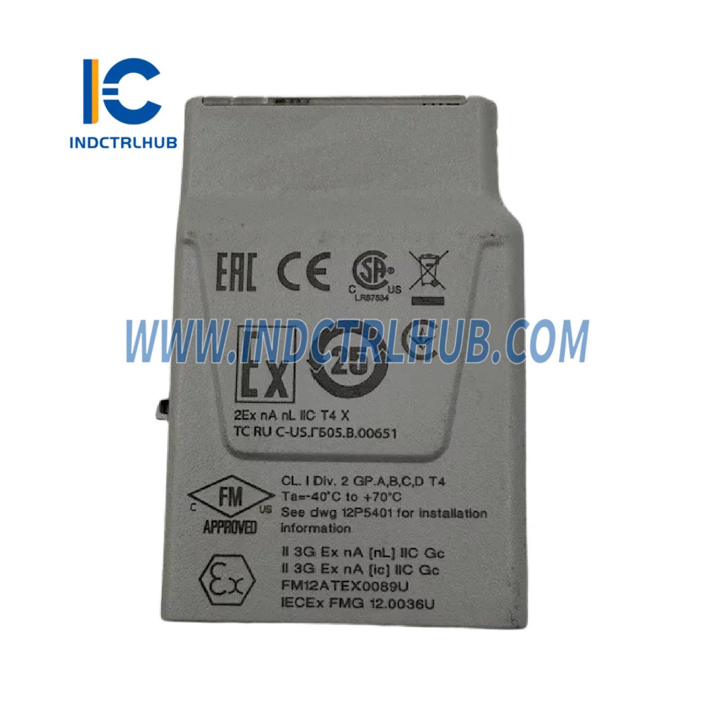
Certifications
| Standard | Details |
|---|---|
| CE | EMC - EN 61326-1 |
| FM (USA) | Class I, Div 2, Groups A, B, C, D, T4; Class I, Zone 2, AEx ec [ic] IIC Gc T4 (FM17US0286U) |
| CSA (Canada) | Class I, Div 2, Groups A, B, C, D, T4; Class I, Zone 2, Ex ec [ic] IIC Gc T4 (FM17CA0145U) |
| ATEX | II 3G Ex nA [nL] IIC Gc; II 3G Ex ec [ic] IIC Gc (FM19ATEX0173U) |
| IEC-Ex | Ex ec [ic] IIC Gc (IECEx FMG 19.0019U) |
| UKEX | FM21UKEX0017U (specific to KL3031X1-BA1) |
| Marine | ABS Certificate of Design Assessment, DNV Marine Certificate |
| Achilles | CIOC: Level 1 (v13.3.1); CIOC2: Level 2 (v14.3) |
Physical & Installation
| Parameter | Details |
|---|---|
| Installation Type | Mounted on CHARM Baseplate (DIN rail) |
| Wiring | 4 screw cage terminals, 0.32_2.5 mm² (22_14 AWG), 7_9 mm strip length (SE4501 Standard Terminal Block) |
| Keying | Keying posts automatically set on first CHARM insertion; can be manually reset to change CHARM type |
| Removal/Insertion | Cannot be removed or inserted with system power energized unless area is non-hazardous; I/O loop assessment required for energy-limited nodes |
| Maintenance | No user-serviceable parts; calibration not required |
Hazardous Area Installation
| Parameter | Details |
|---|---|
| Installation Instructions | Refer to document 12P5403 "DeltaV Electronic Marshalling Digital Automation System (CHARM I/O Subsystem) Zone 2 Installation Instructions" |
| Additional Guidelines | Follow "DeltaV S-series and CHARMs Hardware Installation" manual |
| Hazardous Area Standards | Suitable for Class I, Div 2, Groups A, B, C, D, T4; Class I, Zone 2, AEx/Ex ec [ic] IIC Gc T4; ATEX II 3G Ex nA [nL] IIC Gc and Ex ec [ic] IIC Gc |
Ordering Information
| Description | Model Number |
|---|---|
| RTD/Resistance Input CHARM | SE4303T03 (KL3031X1-BA1) |
| Standard CHARM Terminal Block | SE4501 |
Product Description
Product Overview
| Parameter | Details |
|---|---|
| Product Name | RTD/Resistance Input CHARM |
| Model Numbers | SE4303T03, KL3031X1-BA1 |
| Category | Low Voltage Instrumentation CHARMs |
| Function | Provides input for RTD sensors or resistance measurements |
| System Compatibility | DeltaV v11.3.1 or later (with SD Plus, SX, SQ, MQ, MX, PK Controllers) |
| Terminal Block | Compatible with Standard CHARM Terminal Block (SE4501) |
Hardware & Electrical Specifications
| Specification | Value |
|---|---|
| Sensor Types | RTD: Pt100, Pt200, Pt500, Pt1000, Ni120, Ni100, Ni200, Ni500, Ni1000, Cu10; Resistance: 0 to 2000 Ω (User Defined) |
| Sensor Configuration | 2-wire, 3-wire, or 4-wire |
| Full Scale Signal Range | See Sensor Type Specifications table below |
| Accuracy | See Sensor Type Specifications table below |
| Repeatability | 0.05% of span |
| Resolution | 24-bit A/D converter; resolution depends on sensor type (see table below) |
| Calibration | None required |
| Sensor Excitation Current | 0.5 mA (2-wire and 4-wire); 0.25 mA (3-wire) |
| DC/50/60 Hz Common Mode Rejection | 90 dB typical |
| Isolation | Each sensor galvanically isolated, factory tested to 1000 V DC |
| Open Sensor Detection | Yes |
| CHARM Bus Power | +6.3 V DC at 32 mA max |
| Field Circuit Power | +24 V DC at 10 mA |
| CHARM Power Requirement | 22 mA max @ 24 V DC |
| CHARM Heat Dissipation | 0.30 W |
Sensor Type Specifications
| Sensor Type | Operating Range | 25°C Reference Accuracy | Temperature Drift | Nominal Resolution |
|---|---|---|---|---|
| Pt100 | -200 to 850°C | ±0.25°C | ±0.02°C/°C | ~0.02°C |
| Pt200 | -200 to 850°C | ±0.25°C | ±0.02°C/°C | ~0.02°C |
| Pt500 | -200 to 850°C | ±0.25°C | ±0.02°C/°C | ~0.02°C |
| Pt1000 | -200 to 260°C | ±0.25°C | ±0.02°C/°C | ~0.01°C |
| Ni120 | -80 to 260°C | ±0.15°C | ±0.01°C/°C | ~0.01°C |
| Ni100 | -80 to 260°C | ±0.20°C | ±0.01°C/°C | ~0.01°C |
| Ni200 | -80 to 260°C | ±0.20°C | ±0.01°C/°C | ~0.01°C |
| Ni500 | -80 to 260°C | ±0.20°C | ±0.01°C/°C | ~0.01°C |
| Ni1000 | -80 to 140°C | ±0.20°C | ±0.01°C/°C | ~0.01°C |
| Cu10 | -200 to 260°C | ±0.25°C | ±0.02°C/°C | ~0.01°C |
| Resistance | 0 to 2000 Ω | ±0.25 Ω | ±0.03 Ω/°C | ~0.031 Ω |
Environmental Specifications
| Parameter | Value |
|---|---|
| Operating Temperature | -40 to 70°C (or -40 to 60°C for fanless enclosures) |
| Storage Temperature | -40 to 85°C |
| Relative Humidity | 5 to 95%, non-condensing |
| Protection Rating | IP20 |
| Airborne Contaminants | ISA-S71.04-1985 Class G3, Conformal coating |
| Shock | 10 g ½-sine wave for 11 ms |
| Vibration | 1 mm peak-to-peak from 2 to 13.2 Hz; 0.7 g from 13.2 to 150 Hz |
Functional Features
| Feature |
|---|
| Supports multiple RTD types and resistance measurements (0 to 2000 Ω) |
| Configurable for 2-wire, 3-wire, or 4-wire sensor connections |
| Open sensor detection for fault identification |
| Galvanic isolation for each sensor, tested to 1000 V DC |
| LED Indicators: |
| -_Power/Integrity (Bi-color): Green Solid (Normal), Green Blink (Awaiting configuration), Red Blink (Wiring fault), Red Solid (Internal fault) |
| -_Field Signal (Yellow): Not applicable for analog inputs |
Certifications
| Standard | Details |
|---|---|
| CE | EMC - EN 61326-1 |
| FM (USA) | Class I, Div 2, Groups A, B, C, D, T4; Class I, Zone 2, AEx ec [ic] IIC Gc T4 (FM17US0286U) |
| CSA (Canada) | Class I, Div 2, Groups A, B, C, D, T4; Class I, Zone 2, Ex ec [ic] IIC Gc T4 (FM17CA0145U) |
| ATEX | II 3G Ex nA [nL] IIC Gc; II 3G Ex ec [ic] IIC Gc (FM19ATEX0173U) |
| IEC-Ex | Ex ec [ic] IIC Gc (IECEx FMG 19.0019U) |
| UKEX | FM21UKEX0017U (specific to KL3031X1-BA1) |
| Marine | ABS Certificate of Design Assessment, DNV Marine Certificate |
| Achilles | CIOC: Level 1 (v13.3.1); CIOC2: Level 2 (v14.3) |
Physical & Installation
| Parameter | Details |
|---|---|
| Installation Type | Mounted on CHARM Baseplate (DIN rail) |
| Wiring | 4 screw cage terminals, 0.32_2.5 mm² (22_14 AWG), 7_9 mm strip length (SE4501 Standard Terminal Block) |
| Keying | Keying posts automatically set on first CHARM insertion; can be manually reset to change CHARM type |
| Removal/Insertion | Cannot be removed or inserted with system power energized unless area is non-hazardous; I/O loop assessment required for energy-limited nodes |
| Maintenance | No user-serviceable parts; calibration not required |
Hazardous Area Installation
| Parameter | Details |
|---|---|
| Installation Instructions | Refer to document 12P5403 "DeltaV Electronic Marshalling Digital Automation System (CHARM I/O Subsystem) Zone 2 Installation Instructions" |
| Additional Guidelines | Follow "DeltaV S-series and CHARMs Hardware Installation" manual |
| Hazardous Area Standards | Suitable for Class I, Div 2, Groups A, B, C, D, T4; Class I, Zone 2, AEx/Ex ec [ic] IIC Gc T4; ATEX II 3G Ex nA [nL] IIC Gc and Ex ec [ic] IIC Gc |
Ordering Information
| Description | Model Number |
|---|---|
| RTD/Resistance Input CHARM | SE4303T03 (KL3031X1-BA1) |
| Standard CHARM Terminal Block | SE4501 |