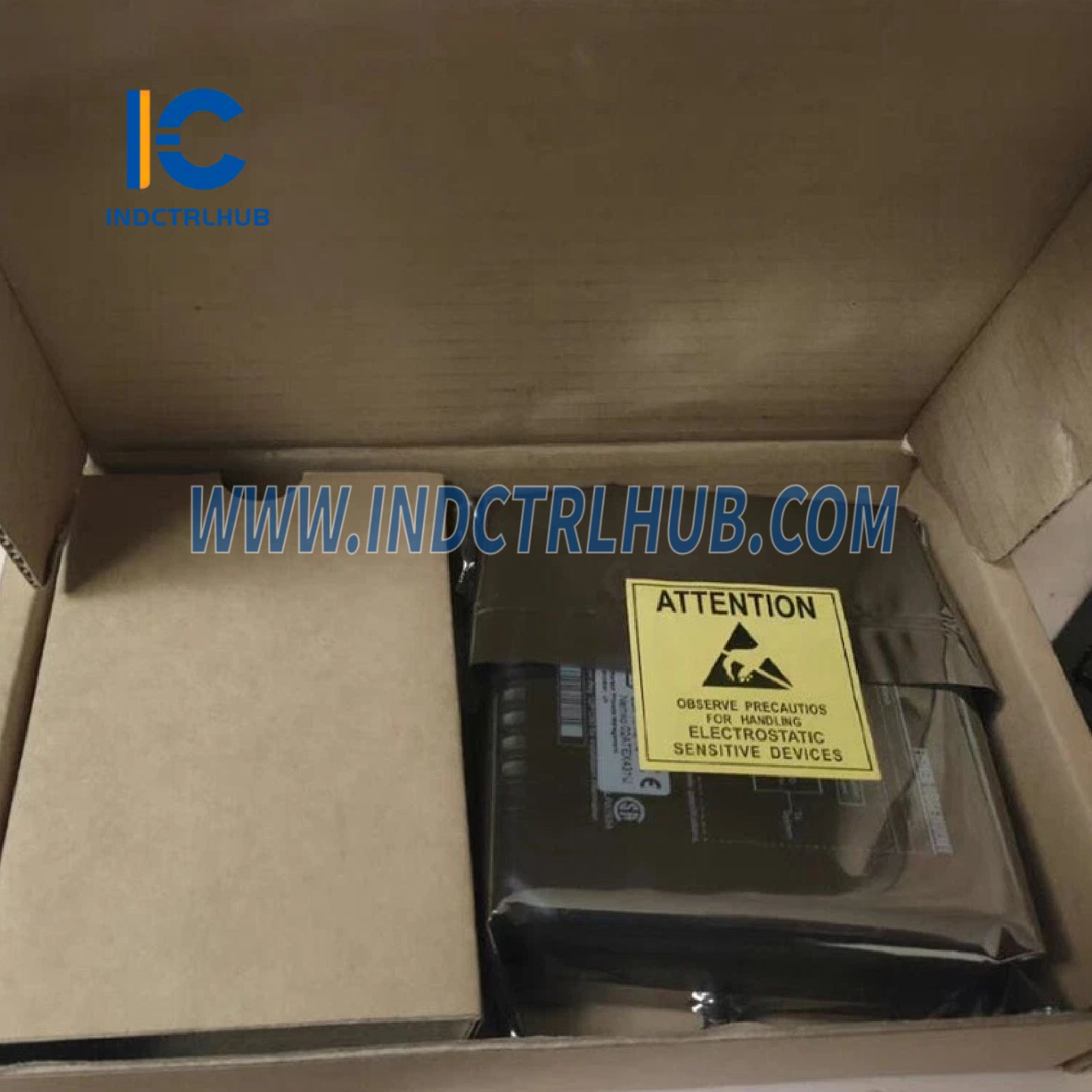
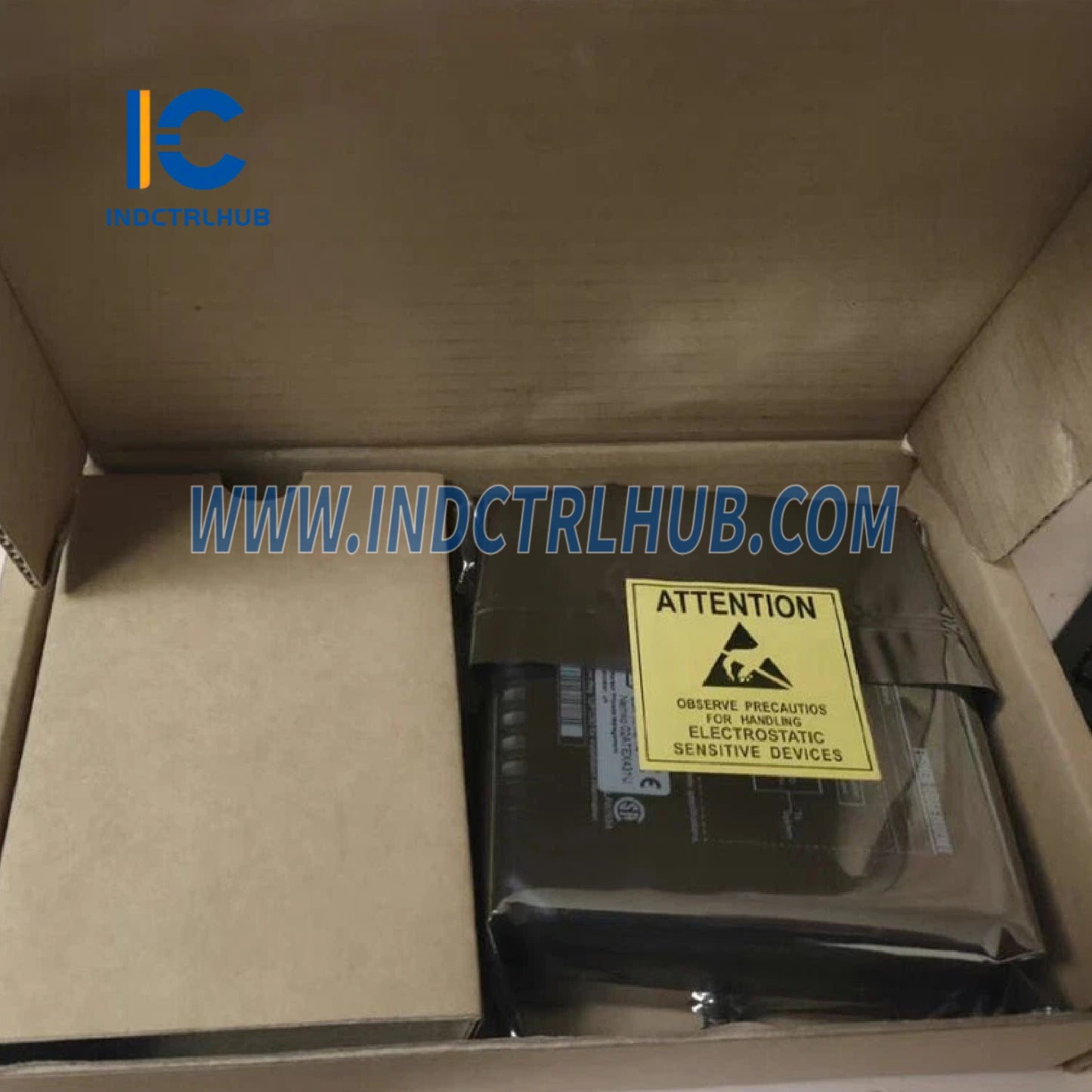
Emerson CE4003S6B1 Analog Input Card
Emerson CE4003S6B1 Analog Input Card
Manufacturer: Emerson
Product No.: CE4003S6B1
Condition:1000 in stock
Product Type: Analog Input Card
Product Origin: USA
Payment: T/T, Western Union
Weight: 1000g
Shipping port: Xiamen
Warranty: 12 months
- 24/7 Support
- 30-Day Returns
- Fast Shipping
Overview
- Model: CE4003S6B1
-
Components:
- Analog Input Card: 8 Channels, RTD
- Termination Block: Resistant Temperature Device (RTD) Termination Block
- Description: Provides 8-channel input for RTD sensors, designed for temperature measurement in process control applications within the DeltaV system.
- Subsystem: DeltaV M-series Traditional I/O
-
Key Features:
- Supports 2, 3, or 4-wire RTD configurations
- Modular, plug-and-play design for easy installation
- Function keying to prevent incorrect card installation
- Online addition without process interruption
- Conformal coating for ISA G3 corrosion resistance
- No manual calibration required
Technical Specifications
Hardware Specifications (RTD Input Card, 8 Channels)
| Parameter | Specification |
|---|---|
| Number of Channels | 8 |
| Sensor Types | Resistance, Pt100, Pt200, Pt500, Ni120, Cu10, User Defined |
| Sensor Configuration | 2-wire, 3-wire, or 4-wire |
| Full Scale Signal Range | See RTD Sensor Type Specifications table below |
| Accuracy | See RTD Sensor Type Specifications table below |
| Repeatability | 0.05% of span |
| A/D Resolution | 16 bits |
| Calibration | None required |
| Units | Degrees C, Degrees F |
| Sensor Excitation Current | 100 µA |
| Common Mode Rejection | 120 dB at 50/60 Hz |
| Common Mode Impedance | >10 megohms |
| Roll-off Frequency | -3 dB at 3 Hz, -25 dB at 30 Hz |
| LocalBus Current (12 VDC Nominal) | 160 mA |
| Open Sensor Detection Time | 1 second |
| Open mV Lead Detection Time | 15 seconds |
| Terminal Block Keying | C3 (specific to RTD Termination Block) |
RTD, Ohms Sensor Type Specifications
| Sensor Type | Full Scale | Operating Range | 25°C Reference Accuracy | Temperature Drift | Resolution |
|---|---|---|---|---|---|
| Resistance | 0 to 2,000 Ω | 0 to 2,000 Ω | ±6.2 Ω | ±0.112 Ω/°C | ~0.02 Ω |
| Pt100 | -200 to 850°C | -200 to 850°C | ±0.5°C | ±0.018°C/°C | ~0.05°C |
| Pt200 | -200 to 850°C | -200 to 850°C | ±0.5°C | ±0.012°C/°C | ~0.05°C |
| Pt500 | -200 to 850°C | -200 to 850°C | ±3.5°C | ±0.063°C/°C | ~0.18°C |
| Ni120 | -70 to 300°C | -70 to 300°C | ±0.2°C | ±0.006°C/°C | ~0.02°C |
| Cu10 | -30 to 140°C | -30 to 140°C | ±2.0°C | ±0.157°C/°C | ~0.23°C |
| User Defined* | 0 to 1,000 Ω | 0 to 1,000 Ω | ±0.4 Ω | ±0.009 Ω/°C | ~0.05 Ω |
| *Note: The Callendar-Van Dusen linearization equation can be used with user-defined Pt RTDs. |
Environmental Specifications
| Parameter | Specification |
|---|---|
| Operating Temperature | 0 to 60°C (32 to 140°F) for standard M-series cards |
| Storage Temperature | -40 to 85°C (-40 to 185°F) |
| Relative Humidity | 5 to 95%, non-condensing |
| Airborne Contaminants | ISA-S71.04-1985 Class G3; conformal coating |
| Protection Rating | IP20, NEMA 12 |
| Hazardous Area/Location | ATEX 3 G IIC T4; Class I, Div 2, Groups A, B, C, D, T4 |
| Shock | 10 g ½-sine wave for 11 ms |
| Vibration | 1 mm peak-to-peak from 2 to 13.2 Hz; 0.7 g from 13.2 to 150 Hz |
| Dimensions | Height: 10.7 cm (4.2 in), Width: 4.1 cm (1.6 in), Depth: 10.5 cm (4.1 in) |
Field Wiring
| Parameter | Specification |
|---|---|
| Field Wiring | Class I, Div 2, Groups A, B, C, D, T4 non-arcing; ATEX 3 G IIC T4 -nA |
| Non-arcing Circuits | Designed to minimize ignition risks during normal operation (excludes energized removal/insertion) |
Functional Specifications
- Redundancy: Not supported for RTD Input Card (simplex mode only, as per page 3).
-
Terminal Block Compatibility:
- RTD Termination Block (included in CE4003S6B1, keyed to C3)
- No mass terminal block or fused terminal block options available for this card (page 24).
- Keying: I/O card keying set to C3, ensuring compatibility with the RTD Termination Block.
- HART Support: Not applicable for RTD cards.
- Pulse Counter: Not applicable for RTD cards.
- Sequence of Events (SOE): Not applicable for RTD cards.
- Linearization: Supports Callendar-Van Dusen linearization for user-defined Pt RTDs.
Installation and Maintenance
-
Installation:
- Plugs into I/O interface carrier (DIN rail-mounted).
- Non-arcing field circuits must be de-energized before removal/insertion in hazardous areas (per Zone 2 instructions, 12P2046, or Class I Div 2 instructions, 12P1293).
- Rotary keying system (C3) ensures correct card-to-terminal block matching.
-
Maintenance:
- No user-serviceable parts; do not disassemble.
- Calibration not required (calibration data stored on card).
-
Replacement:
- In safe areas, cards can be replaced under power.
- In hazardous areas, follow Zone 2 (12P2046) or Class I Div 2 (12P1293) installation instructions.
- Only one card should be removed/inserted at a time.
System Compatibility
- Compatible with: DeltaV M-series controllers.
- Not Compatible with: S-series controller carriers (page 26).
-
Field Wiring:
- Designed for non-arcing circuits in Class I, Div 2 environments.
- ATEX -nA (non-sparking) for hazardous areas, minimizing ignition risks during normal operation (excludes energized removal/insertion).
Ordering Information
| Description | Model Number |
|---|---|
| Analog Input Card: 8 Channels RTD | |
| Resistant Temperature Device (RTD) Termination Block | CE4003S6B1 |
Product Description
Overview
- Model: CE4003S6B1
-
Components:
- Analog Input Card: 8 Channels, RTD
- Termination Block: Resistant Temperature Device (RTD) Termination Block
- Description: Provides 8-channel input for RTD sensors, designed for temperature measurement in process control applications within the DeltaV system.
- Subsystem: DeltaV M-series Traditional I/O
-
Key Features:
- Supports 2, 3, or 4-wire RTD configurations
- Modular, plug-and-play design for easy installation
- Function keying to prevent incorrect card installation
- Online addition without process interruption
- Conformal coating for ISA G3 corrosion resistance
- No manual calibration required
Technical Specifications
Hardware Specifications (RTD Input Card, 8 Channels)
| Parameter | Specification |
|---|---|
| Number of Channels | 8 |
| Sensor Types | Resistance, Pt100, Pt200, Pt500, Ni120, Cu10, User Defined |
| Sensor Configuration | 2-wire, 3-wire, or 4-wire |
| Full Scale Signal Range | See RTD Sensor Type Specifications table below |
| Accuracy | See RTD Sensor Type Specifications table below |
| Repeatability | 0.05% of span |
| A/D Resolution | 16 bits |
| Calibration | None required |
| Units | Degrees C, Degrees F |
| Sensor Excitation Current | 100 µA |
| Common Mode Rejection | 120 dB at 50/60 Hz |
| Common Mode Impedance | >10 megohms |
| Roll-off Frequency | -3 dB at 3 Hz, -25 dB at 30 Hz |
| LocalBus Current (12 VDC Nominal) | 160 mA |
| Open Sensor Detection Time | 1 second |
| Open mV Lead Detection Time | 15 seconds |
| Terminal Block Keying | C3 (specific to RTD Termination Block) |
RTD, Ohms Sensor Type Specifications
| Sensor Type | Full Scale | Operating Range | 25°C Reference Accuracy | Temperature Drift | Resolution |
|---|---|---|---|---|---|
| Resistance | 0 to 2,000 Ω | 0 to 2,000 Ω | ±6.2 Ω | ±0.112 Ω/°C | ~0.02 Ω |
| Pt100 | -200 to 850°C | -200 to 850°C | ±0.5°C | ±0.018°C/°C | ~0.05°C |
| Pt200 | -200 to 850°C | -200 to 850°C | ±0.5°C | ±0.012°C/°C | ~0.05°C |
| Pt500 | -200 to 850°C | -200 to 850°C | ±3.5°C | ±0.063°C/°C | ~0.18°C |
| Ni120 | -70 to 300°C | -70 to 300°C | ±0.2°C | ±0.006°C/°C | ~0.02°C |
| Cu10 | -30 to 140°C | -30 to 140°C | ±2.0°C | ±0.157°C/°C | ~0.23°C |
| User Defined* | 0 to 1,000 Ω | 0 to 1,000 Ω | ±0.4 Ω | ±0.009 Ω/°C | ~0.05 Ω |
| *Note: The Callendar-Van Dusen linearization equation can be used with user-defined Pt RTDs. |
Environmental Specifications
| Parameter | Specification |
|---|---|
| Operating Temperature | 0 to 60°C (32 to 140°F) for standard M-series cards |
| Storage Temperature | -40 to 85°C (-40 to 185°F) |
| Relative Humidity | 5 to 95%, non-condensing |
| Airborne Contaminants | ISA-S71.04-1985 Class G3; conformal coating |
| Protection Rating | IP20, NEMA 12 |
| Hazardous Area/Location | ATEX 3 G IIC T4; Class I, Div 2, Groups A, B, C, D, T4 |
| Shock | 10 g ½-sine wave for 11 ms |
| Vibration | 1 mm peak-to-peak from 2 to 13.2 Hz; 0.7 g from 13.2 to 150 Hz |
| Dimensions | Height: 10.7 cm (4.2 in), Width: 4.1 cm (1.6 in), Depth: 10.5 cm (4.1 in) |
Field Wiring
| Parameter | Specification |
|---|---|
| Field Wiring | Class I, Div 2, Groups A, B, C, D, T4 non-arcing; ATEX 3 G IIC T4 -nA |
| Non-arcing Circuits | Designed to minimize ignition risks during normal operation (excludes energized removal/insertion) |
Functional Specifications
- Redundancy: Not supported for RTD Input Card (simplex mode only, as per page 3).
-
Terminal Block Compatibility:
- RTD Termination Block (included in CE4003S6B1, keyed to C3)
- No mass terminal block or fused terminal block options available for this card (page 24).
- Keying: I/O card keying set to C3, ensuring compatibility with the RTD Termination Block.
- HART Support: Not applicable for RTD cards.
- Pulse Counter: Not applicable for RTD cards.
- Sequence of Events (SOE): Not applicable for RTD cards.
- Linearization: Supports Callendar-Van Dusen linearization for user-defined Pt RTDs.
Installation and Maintenance
-
Installation:
- Plugs into I/O interface carrier (DIN rail-mounted).
- Non-arcing field circuits must be de-energized before removal/insertion in hazardous areas (per Zone 2 instructions, 12P2046, or Class I Div 2 instructions, 12P1293).
- Rotary keying system (C3) ensures correct card-to-terminal block matching.
-
Maintenance:
- No user-serviceable parts; do not disassemble.
- Calibration not required (calibration data stored on card).
-
Replacement:
- In safe areas, cards can be replaced under power.
- In hazardous areas, follow Zone 2 (12P2046) or Class I Div 2 (12P1293) installation instructions.
- Only one card should be removed/inserted at a time.
System Compatibility
- Compatible with: DeltaV M-series controllers.
- Not Compatible with: S-series controller carriers (page 26).
-
Field Wiring:
- Designed for non-arcing circuits in Class I, Div 2 environments.
- ATEX -nA (non-sparking) for hazardous areas, minimizing ignition risks during normal operation (excludes energized removal/insertion).
Ordering Information
| Description | Model Number |
|---|---|
| Analog Input Card: 8 Channels RTD | |
| Resistant Temperature Device (RTD) Termination Block | CE4003S6B1 |