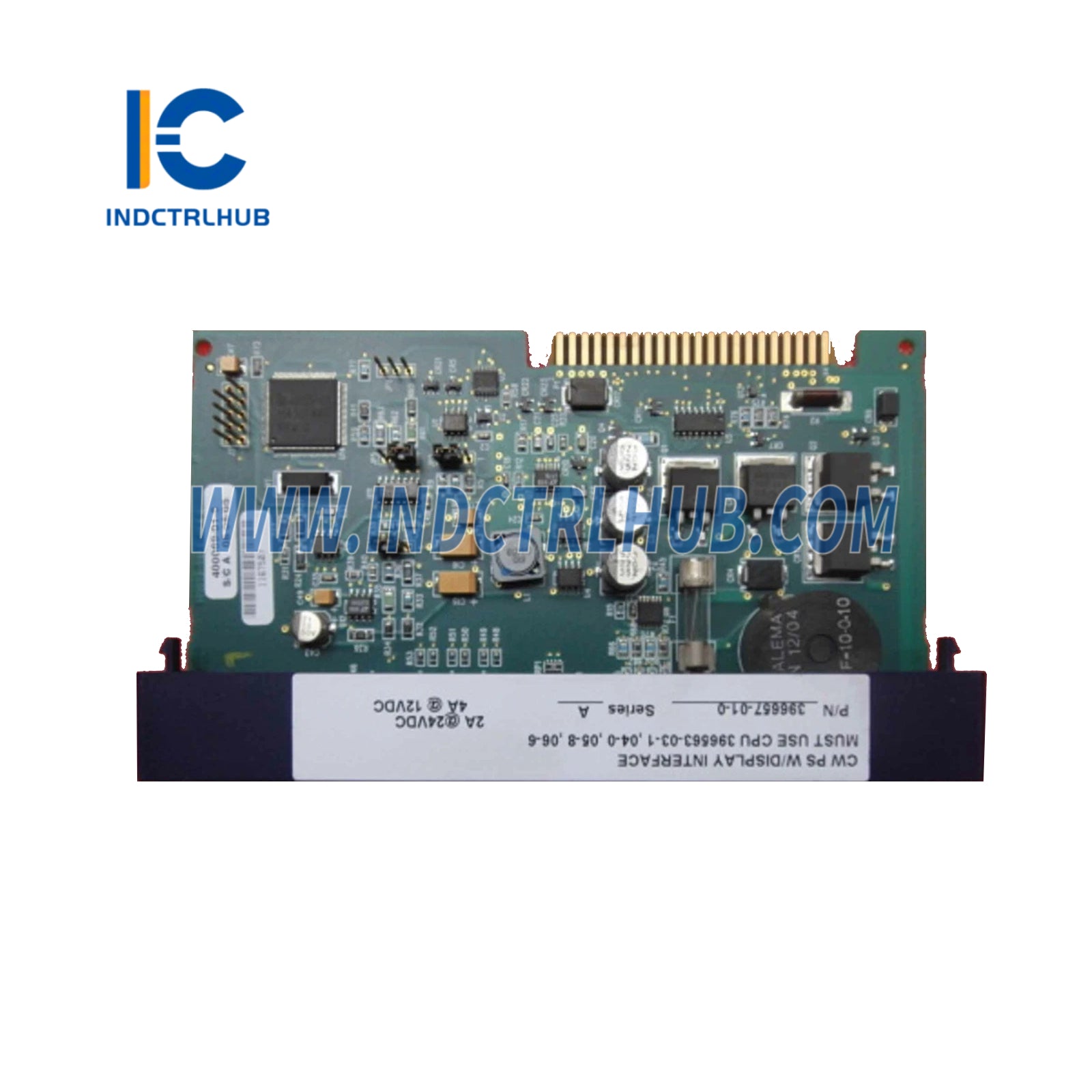
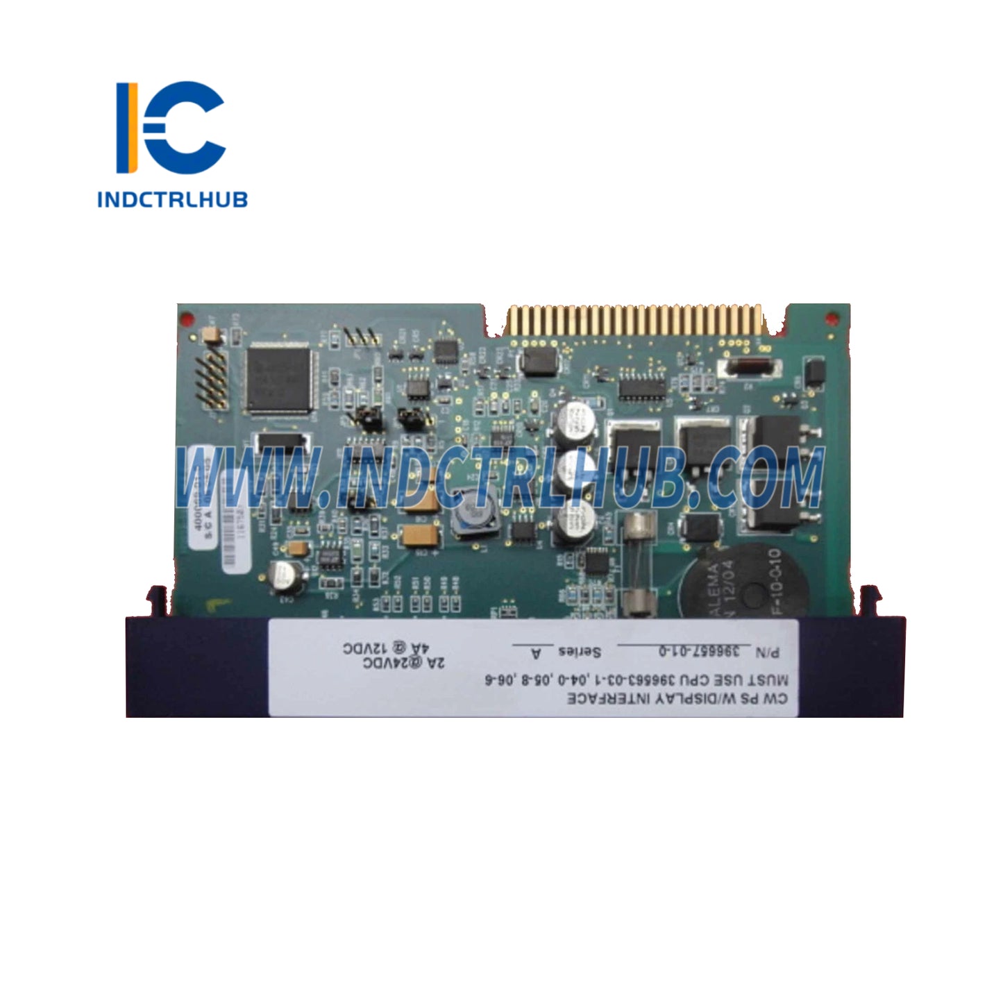
Emerson 396657-01-0 Local Switch & Display Interface
Emerson 396657-01-0 Local Switch & Display Interface
Manufacturer: Emerson
Product No.: 396657-01-0
Condition:1000 in stock
Product Type: Local Switch & Display Interface
Product Origin: USA
Payment: T/T, Western Union
Weight: 1000g
Shipping port: Xiamen
Warranty: 12 months
- 24/7 Support
- 30-Day Returns
- Fast Shipping
Product Overview
| Parameter | Details |
|---|---|
| Product Name | Power Supply/Sequencer Module (PSSM) with Run/Remote/Local Switch & Display Interface |
| Model Number | 396657-01-0, Revision A and above |
| Category | ControlWave Micro - Power Supply and Sequencing |
| Function | Converts and distributes power from an external DC bulk power supply to all modules via the backplane; includes watchdog and status monitoring |
| System Compatibility | ControlWave Micro base housing (3-, 4-, or 8-slot backplanes); slot #1 only |
Hardware Specifications
| Specification | Value |
|---|---|
| Type | Power Supply/Sequencer Module (PSSM) |
| Input Voltage Range | +10.7 to +30 Vdc (12V nominal configuration) or +21.7 to +30 Vdc (24V nominal configuration) |
| Output Voltage | +3.3 Vdc (via DC-to-DC converter) for entire unit; +5 Vdc auxiliary for low power detection and sequencer timing |
| Power Detection | 1200 msec good power detection circuitry |
| Out-of-Spec Detection | Vin out-of-specifications detection circuitry |
| Fuse | 5x20 mm slow blow fuse F1, rated at 3 Amps |
| Watchdog | Optional MOSFET switch connector (TB2) for external alarm/annunciator |
| Connectors | - TB1: Terminal block for external input power - TB2: Watchdog connector for external alarm/annunciator - P1: 44-pin female non-keyed header for backplane connection |
| LED Indicators | - Watchdog (WD) and Idle (IDLE) LEDs on front panel - Six additional LEDs for system status codes |
| Jumpers | - JP2: Power Fail Trip Point (1-2 for 12V, 2-3 for 24V, default 24V) - JP4: Power Supply Shutdown Trip Point (1-2 for 12V, 2-3 for 24V, default 24V) - JP5: Field Voltage Shutdown Trip Point (1-2 for 12V, 2-3 for 24V, default 24V) |
| Switch | Run/Remote/Local keyed switch for operational mode control |
Environmental Specifications
| Parameter | Value |
|---|---|
| Operating Temperature | -40 to +70°C (-40 to +158°F) |
| Humidity | Typical for industrial controllers (e.g., 5-95% non-condensing) |
| Vibration | Meets industrial standards |
| Hazardous Location | Class I, Division 2, Groups A, B, C, D |
Certifications
| Standard | Details |
|---|---|
| UL Listing | Non-incendive, suitable for Class I, Division 2, Groups A, B, C, D hazardous locations |
| Wiring Standards | Complies with National Electrical Code (NFPA 70) Article 501-4(b) for US; Canadian Electrical Code Section 18-152 for Canada |
Physical & Installation
| Parameter | Details |
|---|---|
| Mounting | Plugs into slot #1 of base housing backplane (3-, 4-, or 8-slot) via 44-pin connector (P1) |
| Installation Type | Slide-in module with terminal blocks (TB1, TB2) for wiring; requires housing to be mounted and grounded first |
| Wiring | - TB1: Connects to external bulk DC power supply (+12V or +24V) - TB2: Optional watchdog connector for external alarm/annunciator - Ground: #14 AWG wire from TB1-3 to earth ground recommended |
| Dimensions | Fits within standard ControlWave Micro base housing slot |
| Installation Notes | - Install after housing is mounted and grounded - Configure jumpers (JP2, JP4, JP5) before installation based on input voltage - Suitable for hazardous areas (Class I, Div 2); follow Appendix A instructions |
Functional Features
| Feature |
|---|
| Converts external DC power (+10.7 to +30 Vdc) to +3.3 Vdc for all modules via backplane |
| Supports 12V or 24V nominal input configurations via jumper settings |
| Provides 1200 msec good power detection and out-of-spec detection for reliable operation |
| Includes watchdog MOSFET switch for external alarm/annunciator in case of system failure |
| Features Run/Remote/Local keyed switch for operational mode control |
| Displays system status via WD, IDLE, and six additional LEDs; IDLE LED indicates CPU free time |
| Protected by 3A slow blow fuse (F1) to safeguard the system |
| Supports display interface for optional keypad/display |
| Designed for low power consumption and high reliability in industrial automation |
| Suitable for hazardous locations (Class I, Div 2) with proper wiring and installation |
_
Product Description
Product Overview
| Parameter | Details |
|---|---|
| Product Name | Power Supply/Sequencer Module (PSSM) with Run/Remote/Local Switch & Display Interface |
| Model Number | 396657-01-0, Revision A and above |
| Category | ControlWave Micro - Power Supply and Sequencing |
| Function | Converts and distributes power from an external DC bulk power supply to all modules via the backplane; includes watchdog and status monitoring |
| System Compatibility | ControlWave Micro base housing (3-, 4-, or 8-slot backplanes); slot #1 only |
Hardware Specifications
| Specification | Value |
|---|---|
| Type | Power Supply/Sequencer Module (PSSM) |
| Input Voltage Range | +10.7 to +30 Vdc (12V nominal configuration) or +21.7 to +30 Vdc (24V nominal configuration) |
| Output Voltage | +3.3 Vdc (via DC-to-DC converter) for entire unit; +5 Vdc auxiliary for low power detection and sequencer timing |
| Power Detection | 1200 msec good power detection circuitry |
| Out-of-Spec Detection | Vin out-of-specifications detection circuitry |
| Fuse | 5x20 mm slow blow fuse F1, rated at 3 Amps |
| Watchdog | Optional MOSFET switch connector (TB2) for external alarm/annunciator |
| Connectors | - TB1: Terminal block for external input power - TB2: Watchdog connector for external alarm/annunciator - P1: 44-pin female non-keyed header for backplane connection |
| LED Indicators | - Watchdog (WD) and Idle (IDLE) LEDs on front panel - Six additional LEDs for system status codes |
| Jumpers | - JP2: Power Fail Trip Point (1-2 for 12V, 2-3 for 24V, default 24V) - JP4: Power Supply Shutdown Trip Point (1-2 for 12V, 2-3 for 24V, default 24V) - JP5: Field Voltage Shutdown Trip Point (1-2 for 12V, 2-3 for 24V, default 24V) |
| Switch | Run/Remote/Local keyed switch for operational mode control |
Environmental Specifications
| Parameter | Value |
|---|---|
| Operating Temperature | -40 to +70°C (-40 to +158°F) |
| Humidity | Typical for industrial controllers (e.g., 5-95% non-condensing) |
| Vibration | Meets industrial standards |
| Hazardous Location | Class I, Division 2, Groups A, B, C, D |
Certifications
| Standard | Details |
|---|---|
| UL Listing | Non-incendive, suitable for Class I, Division 2, Groups A, B, C, D hazardous locations |
| Wiring Standards | Complies with National Electrical Code (NFPA 70) Article 501-4(b) for US; Canadian Electrical Code Section 18-152 for Canada |
Physical & Installation
| Parameter | Details |
|---|---|
| Mounting | Plugs into slot #1 of base housing backplane (3-, 4-, or 8-slot) via 44-pin connector (P1) |
| Installation Type | Slide-in module with terminal blocks (TB1, TB2) for wiring; requires housing to be mounted and grounded first |
| Wiring | - TB1: Connects to external bulk DC power supply (+12V or +24V) - TB2: Optional watchdog connector for external alarm/annunciator - Ground: #14 AWG wire from TB1-3 to earth ground recommended |
| Dimensions | Fits within standard ControlWave Micro base housing slot |
| Installation Notes | - Install after housing is mounted and grounded - Configure jumpers (JP2, JP4, JP5) before installation based on input voltage - Suitable for hazardous areas (Class I, Div 2); follow Appendix A instructions |
Functional Features
| Feature |
|---|
| Converts external DC power (+10.7 to +30 Vdc) to +3.3 Vdc for all modules via backplane |
| Supports 12V or 24V nominal input configurations via jumper settings |
| Provides 1200 msec good power detection and out-of-spec detection for reliable operation |
| Includes watchdog MOSFET switch for external alarm/annunciator in case of system failure |
| Features Run/Remote/Local keyed switch for operational mode control |
| Displays system status via WD, IDLE, and six additional LEDs; IDLE LED indicates CPU free time |
| Protected by 3A slow blow fuse (F1) to safeguard the system |
| Supports display interface for optional keypad/display |
| Designed for low power consumption and high reliability in industrial automation |
| Suitable for hazardous locations (Class I, Div 2) with proper wiring and installation |
_