


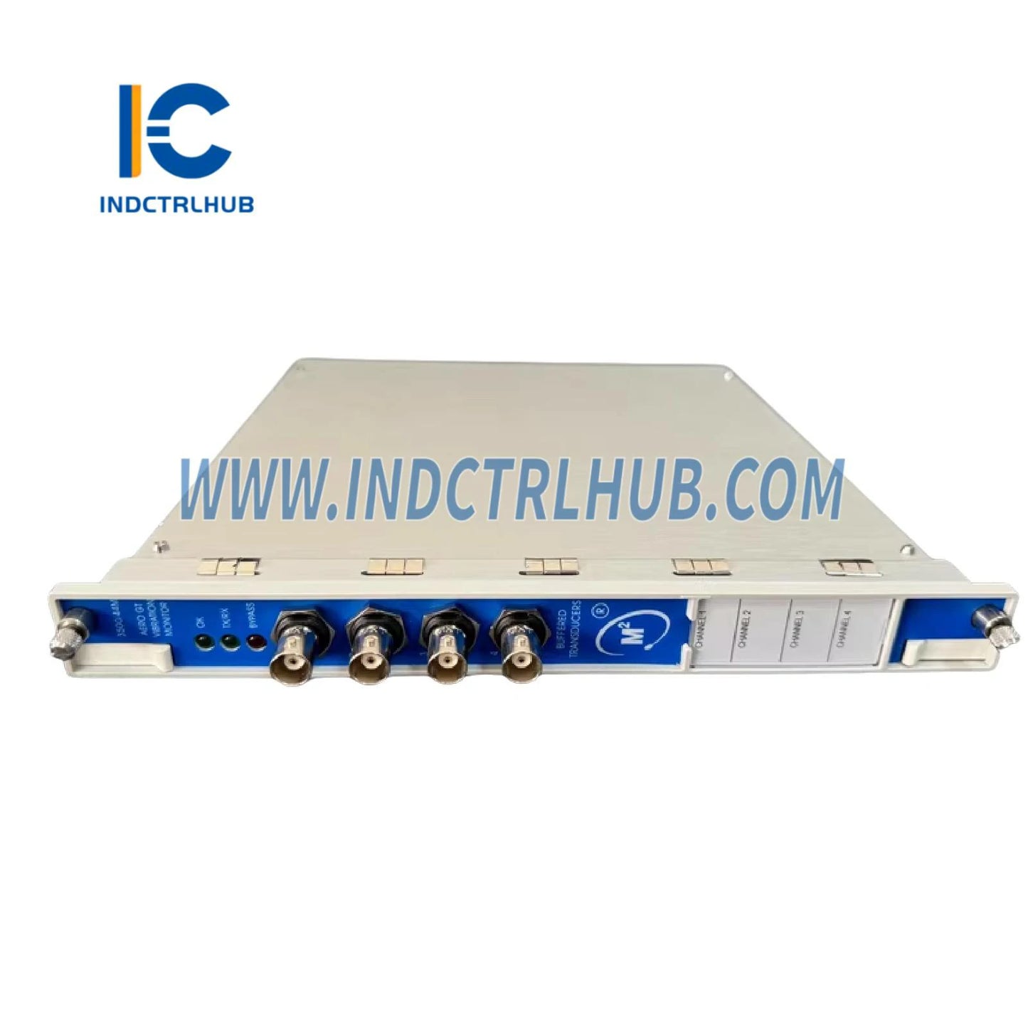
Bently Nevada 3500/46-03-00 176449-06 3500/46M Hydro Monitor
Bently Nevada 3500/46-03-00 176449-06 3500/46M Hydro Monitor
Manufacturer: Bently Nevada
Product No.: 176449-06
Condition:1000 in stock
Product Type: 3500/46M Hydro Monitor
Product Origin: USA
Payment: T/T, Western Union
Weight: 910g
Shipping port: Xiamen
Warranty: 12 months
- 24/7 Support
- 30-Day Returns
- Fast Shipping
Product Overview
| Parameter | Details |
|---|---|
| Part Number | 3500/46-03-00 |
| Spare Part Number | 176449-06 |
| Product Name | 3500/46M Hydro Monitor, Multimode Prox/Velom I/O Module with Internal Terminations |
| System Compatibility | 3500 Machinery Protection System |
Configuration Parameters
| Parameter | Value |
|---|---|
| I/O Module Type | Multimode Prox/Velom I/O Module with Internal Terminations (03) |
| Hazardous Area Approval Option | None (00) |
Inputs
| Parameter | Value |
|---|---|
| Signal | Accepts 1 to 4 proximity, air gap, velocity, or acceleration sensor signals |
| Power Consumption | 7.7 Watts typical |
| Input Impedance | Multimode Prox/Velom I/O: 10 kΩ for Prox/Accel, 3.5 MΩ for Velomitor |
Sensitivity
| Parameter | Value |
|---|---|
| Hydro Radial Vibration and Multimode Hydro RV | 0.79 mV/μm (20 mV/mil), 3.94 mV/μm (100 mV/mil), or 7.87 mV/μm (200 mV/mil) |
| Hydro Air Gap and Multimode Air Gap | 0.20 mV/μm (5 mV/mil), 0.22 mV/μm (5.6 mV/mil), 0.49 mV/μm (12.5 mV/mil), or 0.55 mV/μm (14 mV/mil) |
| Hydro Velocity and Multimode Hydro Velocity | 20 mV/mm/s (508 mV/in/s) |
| Hydro Thrust and Multimode Thrust | 3.94 mV/μm (100 mV/mil), 7.87 mV/μm (200 mV/mil), or 11.22 mV/μm (285 mV/mil) |
| Hydro Acceleration and Multimode Acceleration | 1.02 mV/m/s² (10 mV/g) or 2.55 mV/m/s² (25 mV/g) |
| Hydro Stator End Winding (SEW) | 10.19 mV/m/s² (100 mV/g) |
| Multimode Hydro Dynamic Pressure | Refer to Bently Nevada 350300 Dynamic Pressure Sensor datasheet (110M4613) |
Outputs
| Parameter | Value |
|---|---|
| Front Panel LEDs | OK LED: Indicates proper operation; TX/RX LED: Indicates communication with other modules; Bypass LED: Indicates Bypass Mode |
| Buffered Transducer Outputs | One coaxial connector per channel on the front, short-circuit protected |
| Output Impedance | 550 Ω |
| Transducer Power Supply | Multimode Prox/Velom I/O: -23 Vdc nominal at 43 mA max |
| Recorder | +4 to +20 mA, proportional to monitor full-scale, one output per channel, short-circuit protected |
| Voltage Compliance (Current Output) | 0 to +12 Vdc range across load, load resistance 0 to 600 Ω |
| Resolution | 0.3662 μA per bit, ±0.25% error at room temperature, ±0.7% error over temperature range, update rate _100 ms |
Signal Conditioning
| Parameter | Value |
|---|---|
| Hydro Radial Vibration and Multimode Hydro RV | IX and NX vector filter: Constant Q Filter, minimum rejection in stopband of -50 dB; N value in NX selectable between 2 and 20 (25 cpm to 1,500 cpm) or 2 to 50 (25 cpm to 600 cpm); Composite: NX amplitude multiplied by percent change in gap from zero position for shear pin failure detection |
| Hydro Air Gap and Multimode Air Gap | IX and 2X vector filter: Constant Q Filter, minimum rejection in stopband of -51 dB; Low Mode: 60 to 6,000 cpm; High Mode: 60 to 24,600 cpm; All values except instantaneous Air Gap valid for 1 to 200 poles/second |
| Filter Quality | High-pass: 4-pole (80 dB/decade, 24 dB/octave); Low-pass: 2-pole (40 dB/decade, 12 dB/octave) |
Accuracy
| Parameter | Value |
|---|---|
| Direct and Gap | ±0.33% of full-scale typical, ±1% maximum |
| IX and NX | ±0.33% of full-scale typical, ±1% IX maximum, ±3% NX maximum |
| Average, Minimum, Maximum Air Gap | ±0.33% of full-scale typical, ±1% maximum |
| Hydro Velocity Direct | ±0.33% of full-scale typical, ±1% maximum |
| Hydro Acceleration Direct | ±1% of full-scale maximum (Peak), ±2% of full-scale maximum (RMS) |
| Hydro Dynamic Pressure Static Pressure | ±0.87% of full-scale maximum |
Frequency Response
| Parameter | Value |
|---|---|
| Hydro Velocity Bias | Low Mode: -3 dB at 0.02 Hz; High Mode: -3 dB at 0.07 Hz |
| Hydro Velocity Direct | Low Mode: 0.1875 to 343.75 Hz, -3 dB; High Mode: 0.75 to 1375 Hz, -3 dB |
| Hydro Acceleration Bias | Low-pass filter, -3 dB at 0.01 Hz |
| Hydro Acceleration Not OK Filter | Low-pass filter, -3 dB at 2400 Hz |
| Hydro Acceleration 1X Filter | Constant Q Filter, minimum rejection in stopband of -51 dB, valid for 60 cpm to 60,000 cpm |
| Multimode Acceleration | Non-integrated: RMS 10 to 30,000 Hz, Peak 3 to 30,000 Hz; Integrated: RMS 10 to 20,000 Hz, Peak 3 to 20,000 Hz |
| Hydro Stator End Winding Pole Pass | 2x line frequency (100 Hz or 120 Hz), Constant Q filter (Q=20), minimum rejection in stopband of -60 dB |
Alarms
| Parameter | Value |
|---|---|
| Alarm Setpoints | Adjustable from 0 to 100% of full-scale for each measured value, limited by transducer range; Alert for each active static value, Danger for any two active static values |
| Alarm Accuracy | Within 0.13% of the desired value |
| Alarm Time Delays | Alert: 1 to 400 seconds in one-second intervals; Danger: 1 to 400 seconds in one-second intervals; Multimode channels: Delays set for each measured value with alarm setpoints; Standard channels: One alert and danger delay per channel |
Measured Variables
| Parameter | Value |
|---|---|
| Hydro Radial Vibration | Direct, Gap, 1X Amplitude, 1X Phase Lag, NX Amplitude, NX Phase Lag, Not 1X Amplitude, Composite Amplitude |
| Multimode Hydro RV | Direct, Gap, 1X Amplitude, 1X Phase Lag, NX Amplitude, NX Phase Lag, Not 1X Amplitude, Composite Amplitude, Mode |
| Hydro Air Gap | Average Air Gap, Instantaneous Air Gap, Minimum Air Gap, Maximum Air Gap, Minimum Air Gap Pole Number, Maximum Air Gap Pole Number |
| Multimode Air Gap | Average Air Gap, Instantaneous Air Gap, Minimum Air Gap, Maximum Air Gap, Minimum Air Gap Pole Number, Maximum Air Gap Pole Number, Mode |
| Hydro Velocity | Direct, Bias, 1X Amplitude, 1X Phase Lag, 2X Amplitude, 2X Phase Lag |
| Multimode Hydro Velocity | Direct, Bias, 1X Amplitude, 1X Phase Lag, 2X Amplitude, 2X Phase Lag, Mode |
| Hydro Thrust | Direct, Gap |
| Multimode Thrust | Direct, Gap, Mode |
| Hydro Acceleration | Direct, 1X Amplitude, 2X Amplitude, 1X Phase Lag, 2X Phase Lag |
| Multimode Acceleration | Direct, 1X Amplitude, 2X Amplitude, 1X Phase Lag, 2X Phase Lag, Mode |
| Hydro Stator End Winding | Direct, Pole Pass Amplitude, Direct Resultant, Pole Pass Resultant |
| Multimode Hydro Dynamic Pressure | Direct, Static Pressure, 1X Amplitude, 2X Amplitude, 1X Phase Lag, 2X Phase Lag, Mode |
Physical
| Parameter | Value |
|---|---|
| Monitor Module Dimensions (Height x Width x Depth) | 241.3 mm x 24.4 mm x 241.8 mm (9.50 in x 0.96 in x 9.52 in) |
| Monitor Module Weight | 0.91 kg (2.0 lb) |
| I/O Module Dimensions (Height x Width x Depth) | 241.3 mm x 24.4 mm x 99.1 mm (9.50 in x 0.96 in x 3.90 in) |
| I/O Module Weight | 0.20 kg (0.44 lb) |
Rack Space Requirements
| Parameter | Value |
|---|---|
| Monitor Module | 1 full-height front slot |
| I/O Modules | 1 full-height rear slot |
Firmware and Software Requirements
| Parameter | Value |
|---|---|
| 3500/46M Firmware Version | Multimode Hydro RV, Air Gap, Velocity, Thrust, Acceleration: 2.40; Hydro Stator End Winding: 4.10; Multimode Hydro Dynamic Pressure: 4.21 |
| 3500/01 Software Version | 3.80 for Multimode applications; 3.93 for SEW; 5.20 for Dynamic Pressure |
| 3500/02 Software Version | 2.51 for Multimode applications; 2.52 for SEW |
| 3500/03 Software Version | 1.51 for Multimode applications; 1.52 for SEW |
| 3500/22 Firmware Version | 1.32 for Multimode applications using software commands or 3500/94 display |
| 3500/92 Firmware Version | 1.16 for Multimode applications using software commands |
| System 1 | Required for full multimode support |
| Hardware Requirement | Revision S Multimode I/O Modules for multimode applications using hardware contacts |
_


Product Description
Product Overview
| Parameter | Details |
|---|---|
| Part Number | 3500/46-03-00 |
| Spare Part Number | 176449-06 |
| Product Name | 3500/46M Hydro Monitor, Multimode Prox/Velom I/O Module with Internal Terminations |
| System Compatibility | 3500 Machinery Protection System |
Configuration Parameters
| Parameter | Value |
|---|---|
| I/O Module Type | Multimode Prox/Velom I/O Module with Internal Terminations (03) |
| Hazardous Area Approval Option | None (00) |
Inputs
| Parameter | Value |
|---|---|
| Signal | Accepts 1 to 4 proximity, air gap, velocity, or acceleration sensor signals |
| Power Consumption | 7.7 Watts typical |
| Input Impedance | Multimode Prox/Velom I/O: 10 kΩ for Prox/Accel, 3.5 MΩ for Velomitor |
Sensitivity
| Parameter | Value |
|---|---|
| Hydro Radial Vibration and Multimode Hydro RV | 0.79 mV/μm (20 mV/mil), 3.94 mV/μm (100 mV/mil), or 7.87 mV/μm (200 mV/mil) |
| Hydro Air Gap and Multimode Air Gap | 0.20 mV/μm (5 mV/mil), 0.22 mV/μm (5.6 mV/mil), 0.49 mV/μm (12.5 mV/mil), or 0.55 mV/μm (14 mV/mil) |
| Hydro Velocity and Multimode Hydro Velocity | 20 mV/mm/s (508 mV/in/s) |
| Hydro Thrust and Multimode Thrust | 3.94 mV/μm (100 mV/mil), 7.87 mV/μm (200 mV/mil), or 11.22 mV/μm (285 mV/mil) |
| Hydro Acceleration and Multimode Acceleration | 1.02 mV/m/s² (10 mV/g) or 2.55 mV/m/s² (25 mV/g) |
| Hydro Stator End Winding (SEW) | 10.19 mV/m/s² (100 mV/g) |
| Multimode Hydro Dynamic Pressure | Refer to Bently Nevada 350300 Dynamic Pressure Sensor datasheet (110M4613) |
Outputs
| Parameter | Value |
|---|---|
| Front Panel LEDs | OK LED: Indicates proper operation; TX/RX LED: Indicates communication with other modules; Bypass LED: Indicates Bypass Mode |
| Buffered Transducer Outputs | One coaxial connector per channel on the front, short-circuit protected |
| Output Impedance | 550 Ω |
| Transducer Power Supply | Multimode Prox/Velom I/O: -23 Vdc nominal at 43 mA max |
| Recorder | +4 to +20 mA, proportional to monitor full-scale, one output per channel, short-circuit protected |
| Voltage Compliance (Current Output) | 0 to +12 Vdc range across load, load resistance 0 to 600 Ω |
| Resolution | 0.3662 μA per bit, ±0.25% error at room temperature, ±0.7% error over temperature range, update rate _100 ms |
Signal Conditioning
| Parameter | Value |
|---|---|
| Hydro Radial Vibration and Multimode Hydro RV | IX and NX vector filter: Constant Q Filter, minimum rejection in stopband of -50 dB; N value in NX selectable between 2 and 20 (25 cpm to 1,500 cpm) or 2 to 50 (25 cpm to 600 cpm); Composite: NX amplitude multiplied by percent change in gap from zero position for shear pin failure detection |
| Hydro Air Gap and Multimode Air Gap | IX and 2X vector filter: Constant Q Filter, minimum rejection in stopband of -51 dB; Low Mode: 60 to 6,000 cpm; High Mode: 60 to 24,600 cpm; All values except instantaneous Air Gap valid for 1 to 200 poles/second |
| Filter Quality | High-pass: 4-pole (80 dB/decade, 24 dB/octave); Low-pass: 2-pole (40 dB/decade, 12 dB/octave) |
Accuracy
| Parameter | Value |
|---|---|
| Direct and Gap | ±0.33% of full-scale typical, ±1% maximum |
| IX and NX | ±0.33% of full-scale typical, ±1% IX maximum, ±3% NX maximum |
| Average, Minimum, Maximum Air Gap | ±0.33% of full-scale typical, ±1% maximum |
| Hydro Velocity Direct | ±0.33% of full-scale typical, ±1% maximum |
| Hydro Acceleration Direct | ±1% of full-scale maximum (Peak), ±2% of full-scale maximum (RMS) |
| Hydro Dynamic Pressure Static Pressure | ±0.87% of full-scale maximum |
Frequency Response
| Parameter | Value |
|---|---|
| Hydro Velocity Bias | Low Mode: -3 dB at 0.02 Hz; High Mode: -3 dB at 0.07 Hz |
| Hydro Velocity Direct | Low Mode: 0.1875 to 343.75 Hz, -3 dB; High Mode: 0.75 to 1375 Hz, -3 dB |
| Hydro Acceleration Bias | Low-pass filter, -3 dB at 0.01 Hz |
| Hydro Acceleration Not OK Filter | Low-pass filter, -3 dB at 2400 Hz |
| Hydro Acceleration 1X Filter | Constant Q Filter, minimum rejection in stopband of -51 dB, valid for 60 cpm to 60,000 cpm |
| Multimode Acceleration | Non-integrated: RMS 10 to 30,000 Hz, Peak 3 to 30,000 Hz; Integrated: RMS 10 to 20,000 Hz, Peak 3 to 20,000 Hz |
| Hydro Stator End Winding Pole Pass | 2x line frequency (100 Hz or 120 Hz), Constant Q filter (Q=20), minimum rejection in stopband of -60 dB |
Alarms
| Parameter | Value |
|---|---|
| Alarm Setpoints | Adjustable from 0 to 100% of full-scale for each measured value, limited by transducer range; Alert for each active static value, Danger for any two active static values |
| Alarm Accuracy | Within 0.13% of the desired value |
| Alarm Time Delays | Alert: 1 to 400 seconds in one-second intervals; Danger: 1 to 400 seconds in one-second intervals; Multimode channels: Delays set for each measured value with alarm setpoints; Standard channels: One alert and danger delay per channel |
Measured Variables
| Parameter | Value |
|---|---|
| Hydro Radial Vibration | Direct, Gap, 1X Amplitude, 1X Phase Lag, NX Amplitude, NX Phase Lag, Not 1X Amplitude, Composite Amplitude |
| Multimode Hydro RV | Direct, Gap, 1X Amplitude, 1X Phase Lag, NX Amplitude, NX Phase Lag, Not 1X Amplitude, Composite Amplitude, Mode |
| Hydro Air Gap | Average Air Gap, Instantaneous Air Gap, Minimum Air Gap, Maximum Air Gap, Minimum Air Gap Pole Number, Maximum Air Gap Pole Number |
| Multimode Air Gap | Average Air Gap, Instantaneous Air Gap, Minimum Air Gap, Maximum Air Gap, Minimum Air Gap Pole Number, Maximum Air Gap Pole Number, Mode |
| Hydro Velocity | Direct, Bias, 1X Amplitude, 1X Phase Lag, 2X Amplitude, 2X Phase Lag |
| Multimode Hydro Velocity | Direct, Bias, 1X Amplitude, 1X Phase Lag, 2X Amplitude, 2X Phase Lag, Mode |
| Hydro Thrust | Direct, Gap |
| Multimode Thrust | Direct, Gap, Mode |
| Hydro Acceleration | Direct, 1X Amplitude, 2X Amplitude, 1X Phase Lag, 2X Phase Lag |
| Multimode Acceleration | Direct, 1X Amplitude, 2X Amplitude, 1X Phase Lag, 2X Phase Lag, Mode |
| Hydro Stator End Winding | Direct, Pole Pass Amplitude, Direct Resultant, Pole Pass Resultant |
| Multimode Hydro Dynamic Pressure | Direct, Static Pressure, 1X Amplitude, 2X Amplitude, 1X Phase Lag, 2X Phase Lag, Mode |
Physical
| Parameter | Value |
|---|---|
| Monitor Module Dimensions (Height x Width x Depth) | 241.3 mm x 24.4 mm x 241.8 mm (9.50 in x 0.96 in x 9.52 in) |
| Monitor Module Weight | 0.91 kg (2.0 lb) |
| I/O Module Dimensions (Height x Width x Depth) | 241.3 mm x 24.4 mm x 99.1 mm (9.50 in x 0.96 in x 3.90 in) |
| I/O Module Weight | 0.20 kg (0.44 lb) |
Rack Space Requirements
| Parameter | Value |
|---|---|
| Monitor Module | 1 full-height front slot |
| I/O Modules | 1 full-height rear slot |
Firmware and Software Requirements
| Parameter | Value |
|---|---|
| 3500/46M Firmware Version | Multimode Hydro RV, Air Gap, Velocity, Thrust, Acceleration: 2.40; Hydro Stator End Winding: 4.10; Multimode Hydro Dynamic Pressure: 4.21 |
| 3500/01 Software Version | 3.80 for Multimode applications; 3.93 for SEW; 5.20 for Dynamic Pressure |
| 3500/02 Software Version | 2.51 for Multimode applications; 2.52 for SEW |
| 3500/03 Software Version | 1.51 for Multimode applications; 1.52 for SEW |
| 3500/22 Firmware Version | 1.32 for Multimode applications using software commands or 3500/94 display |
| 3500/92 Firmware Version | 1.16 for Multimode applications using software commands |
| System 1 | Required for full multimode support |
| Hardware Requirement | Revision S Multimode I/O Modules for multimode applications using hardware contacts |
_