
Bently Nevada 3500/25 Enhanced Keyphasor Module | 126398-01H
Bently Nevada 3500/25 Enhanced Keyphasor Module | 126398-01H
Manufacturer: Bently Nevada
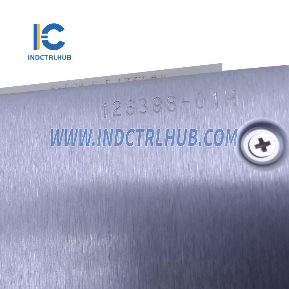
Product No.: 126398-01H
Condition:1000 in stock
Product Type: Keyphasor Signal Processor
Product Origin: 126398-01H
Payment: T/T, Western Union
Weight: 340g
Shipping port: Xiamen
Warranty: 12 months
- 24/7 Support
- 30-Day Returns
- Fast Shipping
🔄 Precision Shaft Timing Reference for Advanced Vibration Diagnostics
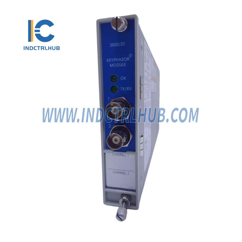
The Bently Nevada 3500/25 Enhanced Keyphasor Module (Part Number: 126398-01H) serves as the critical timing heartbeat of your machinery protection system. This half-height, dual-channel module transforms raw proximity probe or magnetic pickup signals into precision digital Keyphasor marks—enabling phase-referenced vibration analysis that reveals the exact angular location of shaft defects, imbalance, and misalignment.
⚡ What Makes Keyphasor Technology Essential?
Phase Information = Root Cause Clarity: While vibration amplitude tells you how much a shaft is moving, Keyphasor timing reveals where the problem is located on the rotating assembly. This angular reference is indispensable for balancing operations, identifying bent shafts, detecting rubs, and diagnosing coupling misalignment.
Orbit Analysis Foundation: The module's digital timing marks enable XY orbit plots that visualize shaft motion patterns—the gold standard for diagnosing complex rotor dynamics issues in turbomachinery.
✅ Dual-Channel Capacity
Monitor two independent shafts or implement redundant timing on critical machines—all from a single half-height module slot.
🔌 Universal Input Compatibility
Accepts signals from proximity probes (+0.8V to -21V) and magnetic pickups (isolated I/O: +5V to -11V) with automatic signal conditioning.
⚙️ Low-Speed Capability
Magnetic pickup mode operates down to 200 RPM (3.3 Hz)—ideal for startup/shutdown monitoring and slow-roll compensation.
📊 Scalable Architecture
Normal config: 4 Keyphasor signals | Paired config: 8 Keyphasor signals for multi-train monitoring.
📐 Technical Specifications
| Parameter | Specification |
|---|---|
| Model Number | 3500/25-126398-01H |
| Channel Count | 2 independent Keyphasor inputs |
| Module Height | Half-height (allows pairing with another half-height module) |
| Power Consumption | 3.2 Watts typical |
| Input Impedance | 21.8 kΩ minimum |
| Signal Range (Non-Isolated) | +0.8V to -21.0V (proximity probes) |
| Signal Range (Isolated) | +5V to -11V (magnetic pickups) |
| Minimum Speed (Mag Pickup) | 200 RPM (3.3 Hz) |
| Dimensions (H×W×D) | 119.9 × 24.4 × 256.5 mm (4.72" × 0.96" × 10.10") |
| Weight | 0.34 kg (0.76 lb) |
🏭 Real-World Application Scenarios
🔧 Turbine Balancing Operations
Challenge: A 50 MW steam turbine exhibits 8 mils of vibration at 3600 RPM. Amplitude data alone cannot determine whether the issue is mass imbalance, thermal bow, or coupling misalignment.
Solution: The 3500/25 module provides once-per-revolution timing marks from a shaft-mounted reflective tape. When correlated with radial vibration data, the phase angle reveals the heavy spot is at 47° from the Keyphasor mark—confirming mass imbalance and enabling precision weight placement during the next outage.
Outcome: Vibration reduced to 1.2 mils after single-plane balancing, avoiding a costly two-plane balance procedure.
⚙️ Compressor Startup Monitoring
Challenge: A centrifugal compressor train must pass through multiple critical speeds during startup. Operators need real-time orbit plots to verify the rotor is not contacting stationary components.
Solution: Dual Keyphasor channels monitor both the compressor and gearbox shafts simultaneously. The module's 200 RPM minimum speed capability ensures valid timing marks from initial rotation through full operating speed (12,000 RPM).
Outcome: XY orbit analysis during startup reveals a tight, circular pattern—confirming safe passage through critical speeds without rubs or instabilities.
🌊 Hydro Turbine Wicket Gate Diagnostics
Challenge: A hydroelectric turbine shows erratic vibration patterns that don't correlate with load changes. Suspected cause is uneven wicket gate positioning creating hydraulic imbalance.
Solution: The Keyphasor module processes signals from a magnetic pickup mounted near the runner. Phase-referenced vibration data reveals a 1X component that shifts 180° when wicket gates move from 40% to 60% opening—confirming hydraulic imbalance rather than mechanical defects.
Outcome: Wicket gate linkage adjustment eliminates the phase shift, restoring smooth operation across the full load range.
🔌 Configuration & Integration Workflow
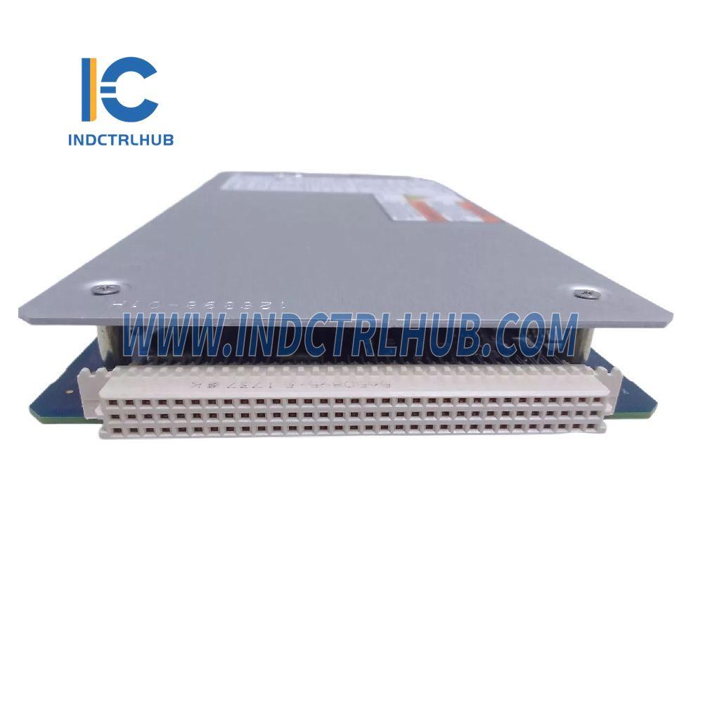
- Module Installation: Insert 3500/25 into any available half-height slot to the right of the TDI module in your 3500 rack.
- I/O Module Selection: Choose internal termination (field wiring direct to module rear) or external termination (junction box) based on installation accessibility.
- Transducer Connection: Wire proximity probe or magnetic pickup to designated channel terminals. For magnetic pickups, use isolated I/O modules (option 04 or 05).
- Software Configuration: Use 3500 Rack Configuration Software to set trigger thresholds, hysteresis levels, and assign Keyphasor signals to monitor channels requiring phase reference.
- Validation Testing: Verify Keyphasor LED flashes once per shaft revolution. Confirm phase angle readings in System 1 software match expected values for known shaft positions.
📦 Ordering Configuration Decoder
Part Number Format: 3500/25-AA-BB-CC
| Code | Option | Description |
|---|---|---|
| AA | 01 | Single 2-channel Keyphasor card (2 channels total) |
| AA | 02 | Two 2-channel Keyphasor cards (4 channels total) |
| BB | 01 | Internal terminations (proximity probes) |
| BB | 02 | External terminations (proximity probes) |
| BB | 04 | Isolated I/O, internal terminations (magnetic pickups) |
| BB | 05 | Isolated I/O, external terminations (magnetic pickups) |
| CC | 00 | No hazardous area certification |
| CC | 01 | cNRTLus (Class 1, Division 2) |
| CC | 02 | ATEX/IECEx/CSA (Class 1, Zone 2) |
💡 Why Phase-Referenced Analysis Matters
Imbalance vs. Misalignment: Both produce 1X vibration, but imbalance shows consistent phase across all measurement planes while misalignment exhibits 180° phase shifts between coupling ends.
Rub Detection: Intermittent contact between rotating and stationary parts creates sudden phase changes that are invisible in amplitude-only monitoring.
Thermal Growth Tracking: As machines heat up, shaft centerline position shifts. Keyphasor-referenced orbit plots reveal whether thermal expansion is causing bearing misalignment.
🔗 System Integration Ecosystem
| 3500/40M Proximitor Monitor | Receives Keyphasor timing to generate phase-tagged vibration vectors for balancing calculations |
| 3500/42M Proximitor/Seismic Monitor | Uses Keyphasor reference for XY orbit generation and slow-roll compensation |
| 3500/22 TDI Module | Captures time-stamped Keyphasor events during transient conditions (startups, trips, load changes) |
| System 1 Software | Displays real-time orbit plots, Bode diagrams, and polar plots using Keyphasor timing data |
⚠️ Critical Installation Notes
- Transducer Alignment: Keyphasor probe must view a single, distinct shaft feature (notch, keyway, or reflective tape). Multiple features per revolution will generate false triggers.
- Signal Polarity: Proximity probe Keyphasor signals are negative-going pulses. Magnetic pickup signals are AC waveforms—module automatically detects zero-crossings.
- Grounding: Use single-point grounding at the monitor rack. Multiple ground paths can introduce noise that corrupts timing accuracy.
- Cable Routing: Keep Keyphasor cables separated from high-voltage power lines (>300mm clearance) to prevent EMI-induced jitter.
📦 Package Contents
- ✅ 3500/25 Enhanced Keyphasor Module main board (126398-01H)
- ✅ I/O interface module (configuration per order code)
- ✅ Rack mounting hardware and retention clips
- ✅ Configuration quick-start guide
- ✅ Keyphasor signal wiring diagram
🎯 Engineering Support: Our vibration specialists provide complimentary application assistance including transducer selection, trigger threshold optimization, and phase angle interpretation training. Contact us for pre-installation consultation or post-commissioning troubleshooting.


Product Description
🔄 Precision Shaft Timing Reference for Advanced Vibration Diagnostics
The Bently Nevada 3500/25 Enhanced Keyphasor Module (Part Number: 126398-01H) serves as the critical timing heartbeat of your machinery protection system. This half-height, dual-channel module transforms raw proximity probe or magnetic pickup signals into precision digital Keyphasor marks—enabling phase-referenced vibration analysis that reveals the exact angular location of shaft defects, imbalance, and misalignment.
⚡ What Makes Keyphasor Technology Essential?
Phase Information = Root Cause Clarity: While vibration amplitude tells you how much a shaft is moving, Keyphasor timing reveals where the problem is located on the rotating assembly. This angular reference is indispensable for balancing operations, identifying bent shafts, detecting rubs, and diagnosing coupling misalignment.
Orbit Analysis Foundation: The module's digital timing marks enable XY orbit plots that visualize shaft motion patterns—the gold standard for diagnosing complex rotor dynamics issues in turbomachinery.
✅ Dual-Channel Capacity
Monitor two independent shafts or implement redundant timing on critical machines—all from a single half-height module slot.
🔌 Universal Input Compatibility
Accepts signals from proximity probes (+0.8V to -21V) and magnetic pickups (isolated I/O: +5V to -11V) with automatic signal conditioning.
⚙️ Low-Speed Capability
Magnetic pickup mode operates down to 200 RPM (3.3 Hz)—ideal for startup/shutdown monitoring and slow-roll compensation.
📊 Scalable Architecture
Normal config: 4 Keyphasor signals | Paired config: 8 Keyphasor signals for multi-train monitoring.
📐 Technical Specifications
| Parameter | Specification |
|---|---|
| Model Number | 3500/25-126398-01H |
| Channel Count | 2 independent Keyphasor inputs |
| Module Height | Half-height (allows pairing with another half-height module) |
| Power Consumption | 3.2 Watts typical |
| Input Impedance | 21.8 kΩ minimum |
| Signal Range (Non-Isolated) | +0.8V to -21.0V (proximity probes) |
| Signal Range (Isolated) | +5V to -11V (magnetic pickups) |
| Minimum Speed (Mag Pickup) | 200 RPM (3.3 Hz) |
| Dimensions (H×W×D) | 119.9 × 24.4 × 256.5 mm (4.72" × 0.96" × 10.10") |
| Weight | 0.34 kg (0.76 lb) |
🏭 Real-World Application Scenarios
🔧 Turbine Balancing Operations
Challenge: A 50 MW steam turbine exhibits 8 mils of vibration at 3600 RPM. Amplitude data alone cannot determine whether the issue is mass imbalance, thermal bow, or coupling misalignment.
Solution: The 3500/25 module provides once-per-revolution timing marks from a shaft-mounted reflective tape. When correlated with radial vibration data, the phase angle reveals the heavy spot is at 47° from the Keyphasor mark—confirming mass imbalance and enabling precision weight placement during the next outage.
Outcome: Vibration reduced to 1.2 mils after single-plane balancing, avoiding a costly two-plane balance procedure.
⚙️ Compressor Startup Monitoring
Challenge: A centrifugal compressor train must pass through multiple critical speeds during startup. Operators need real-time orbit plots to verify the rotor is not contacting stationary components.
Solution: Dual Keyphasor channels monitor both the compressor and gearbox shafts simultaneously. The module's 200 RPM minimum speed capability ensures valid timing marks from initial rotation through full operating speed (12,000 RPM).
Outcome: XY orbit analysis during startup reveals a tight, circular pattern—confirming safe passage through critical speeds without rubs or instabilities.
🌊 Hydro Turbine Wicket Gate Diagnostics
Challenge: A hydroelectric turbine shows erratic vibration patterns that don't correlate with load changes. Suspected cause is uneven wicket gate positioning creating hydraulic imbalance.
Solution: The Keyphasor module processes signals from a magnetic pickup mounted near the runner. Phase-referenced vibration data reveals a 1X component that shifts 180° when wicket gates move from 40% to 60% opening—confirming hydraulic imbalance rather than mechanical defects.
Outcome: Wicket gate linkage adjustment eliminates the phase shift, restoring smooth operation across the full load range.
🔌 Configuration & Integration Workflow
- Module Installation: Insert 3500/25 into any available half-height slot to the right of the TDI module in your 3500 rack.
- I/O Module Selection: Choose internal termination (field wiring direct to module rear) or external termination (junction box) based on installation accessibility.
- Transducer Connection: Wire proximity probe or magnetic pickup to designated channel terminals. For magnetic pickups, use isolated I/O modules (option 04 or 05).
- Software Configuration: Use 3500 Rack Configuration Software to set trigger thresholds, hysteresis levels, and assign Keyphasor signals to monitor channels requiring phase reference.
- Validation Testing: Verify Keyphasor LED flashes once per shaft revolution. Confirm phase angle readings in System 1 software match expected values for known shaft positions.
📦 Ordering Configuration Decoder
Part Number Format: 3500/25-AA-BB-CC
| Code | Option | Description |
|---|---|---|
| AA | 01 | Single 2-channel Keyphasor card (2 channels total) |
| AA | 02 | Two 2-channel Keyphasor cards (4 channels total) |
| BB | 01 | Internal terminations (proximity probes) |
| BB | 02 | External terminations (proximity probes) |
| BB | 04 | Isolated I/O, internal terminations (magnetic pickups) |
| BB | 05 | Isolated I/O, external terminations (magnetic pickups) |
| CC | 00 | No hazardous area certification |
| CC | 01 | cNRTLus (Class 1, Division 2) |
| CC | 02 | ATEX/IECEx/CSA (Class 1, Zone 2) |
💡 Why Phase-Referenced Analysis Matters
Imbalance vs. Misalignment: Both produce 1X vibration, but imbalance shows consistent phase across all measurement planes while misalignment exhibits 180° phase shifts between coupling ends.
Rub Detection: Intermittent contact between rotating and stationary parts creates sudden phase changes that are invisible in amplitude-only monitoring.
Thermal Growth Tracking: As machines heat up, shaft centerline position shifts. Keyphasor-referenced orbit plots reveal whether thermal expansion is causing bearing misalignment.
🔗 System Integration Ecosystem
| 3500/40M Proximitor Monitor | Receives Keyphasor timing to generate phase-tagged vibration vectors for balancing calculations |
| 3500/42M Proximitor/Seismic Monitor | Uses Keyphasor reference for XY orbit generation and slow-roll compensation |
| 3500/22 TDI Module | Captures time-stamped Keyphasor events during transient conditions (startups, trips, load changes) |
| System 1 Software | Displays real-time orbit plots, Bode diagrams, and polar plots using Keyphasor timing data |
⚠️ Critical Installation Notes
- Transducer Alignment: Keyphasor probe must view a single, distinct shaft feature (notch, keyway, or reflective tape). Multiple features per revolution will generate false triggers.
- Signal Polarity: Proximity probe Keyphasor signals are negative-going pulses. Magnetic pickup signals are AC waveforms—module automatically detects zero-crossings.
- Grounding: Use single-point grounding at the monitor rack. Multiple ground paths can introduce noise that corrupts timing accuracy.
- Cable Routing: Keep Keyphasor cables separated from high-voltage power lines (>300mm clearance) to prevent EMI-induced jitter.
📦 Package Contents
- ✅ 3500/25 Enhanced Keyphasor Module main board (126398-01H)
- ✅ I/O interface module (configuration per order code)
- ✅ Rack mounting hardware and retention clips
- ✅ Configuration quick-start guide
- ✅ Keyphasor signal wiring diagram
🎯 Engineering Support: Our vibration specialists provide complimentary application assistance including transducer selection, trigger threshold optimization, and phase angle interpretation training. Contact us for pre-installation consultation or post-commissioning troubleshooting.