


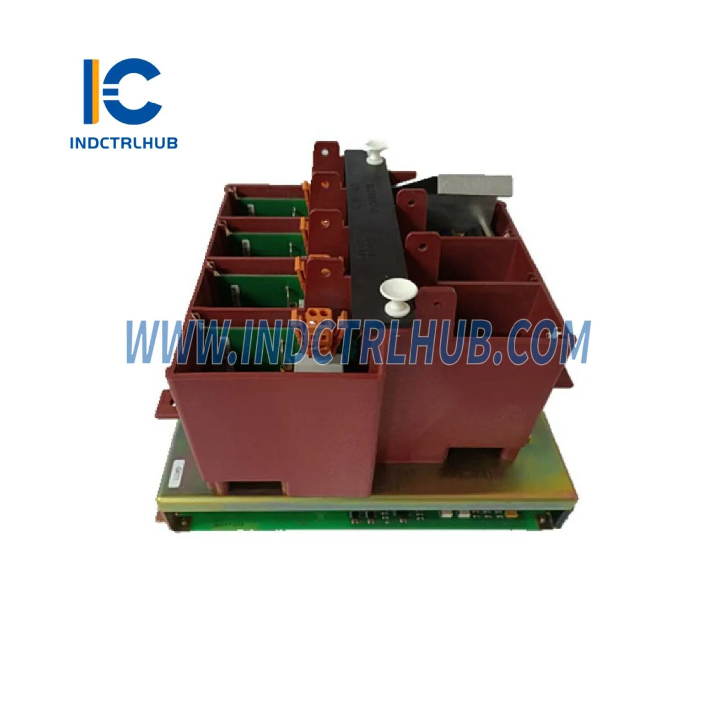
3BHB005243R0105 | ABB C755 AE105 Gate Unit Power for ACS6000
3BHB005243R0105 | ABB C755 AE105 Gate Unit Power for ACS6000
Manufacturer: ABB
Product No.: 3BHB005243R0105
Condition:1000 in stock
Product Type: Gate Unit Power
Product Origin: 3005243000016
Payment: T/T, Western Union
Weight: 3650g
Shipping port: Xiamen
Warranty: 12 months
- 24/7 Support
- 30-Day Returns
- Fast Shipping
ABB C755 AE105 Gate Unit Power - Precision IGCT Gate Driver for ACS6000 Drives
The ABB C755 AE105 Gate Unit Power (Part Number: 3BHB005243R0105) represents a critical power electronics component engineered for ABB's ACS6000 series medium voltage AC drives. This Swiss-manufactured gate driver module delivers precise IGCT (Integrated Gate-Commutated Thyristor) triggering pulses with microsecond-level timing accuracy, enabling reliable high-power switching in industrial drive systems ranging from 315 kW to 27 MW.
Product Identification & Classification
| Attribute | Value |
|---|---|
| ABB Part Number | 3BHB005243R0105 |
| Type Designation | S KU C755 AE105:GUSP |
| Product Category | Gate Unit Power (IGCT Driver Module) |
| Application Platform | ACS6000 Medium Voltage AC Drives |
| Replaces Legacy Part | HB005243R0105 (obsolete) |
| Manufacturing Origin | Switzerland (CH) |
| HS Customs Code | 85049099 |
| Product Condition | New, Factory Sealed |
| Minimum Order Quantity | 1 piece |
| Unit Weight | 3.65 kg |
Functional Overview & Operating Principle
Gate Driver Architecture
The C755 AE105 gate unit employs a dual-channel isolated gate driver topology specifically optimized for ABB's 5SHY series IGCT modules. Each driver channel incorporates:
- Fiber Optic Signal Reception: Galvanically isolated command input from the drive control board eliminates ground loop interference and provides >10 kV isolation voltage
- High-Current Gate Pulse Generation: Delivers peak gate currents of 15-25A with sub-100ns rise times to ensure rapid IGCT turn-on and minimize switching losses
- Negative Gate Bias Supply: Maintains -15V reverse bias during off-state to prevent spurious turn-on from dv/dt transients in high-voltage applications
- Desaturation Protection: Monitors IGCT collector-emitter voltage during conduction to detect short-circuit conditions and trigger protective shutdown within 2-3 microseconds
- Gate Monitoring Feedback: Returns gate voltage and current waveforms to the control system for diagnostic analysis and predictive maintenance algorithms
Power Supply Architecture
The gate unit integrates a multi-output isolated DC-DC converter that derives power from the drive's auxiliary 24VDC rail and generates:
- +15V @ 2A for gate driver logic and fiber optic receivers
- +20V @ 5A for positive gate drive pulses
- -15V @ 3A for negative gate bias and desaturation detection
- Auxiliary ±5V rails for analog signal conditioning circuits
All outputs feature overcurrent foldback protection and thermal shutdown to prevent damage during fault conditions.
Electrical & Performance Specifications
| Parameter | Specification |
|---|---|
| Input Voltage (Auxiliary Power) | 24 VDC ±20% (19.2-28.8 VDC) |
| Input Current (Typical) | 3.5 A @ 24 VDC (84W total power consumption) |
| Input Current (Peak) | 8 A during gate pulse events |
| Gate Pulse Output Voltage | +20 VDC (turn-on), -15 VDC (turn-off/bias) |
| Gate Pulse Peak Current | 15-25 A (adjustable via external resistor) |
| Gate Pulse Rise Time | <100 ns (10%-90%) |
| Gate Pulse Fall Time | <150 ns (90%-10%) |
| Maximum Pulse Frequency | 10 kHz (PWM switching frequency) |
| Minimum Pulse Width | 500 ns (guaranteed triggering) |
| Propagation Delay | <200 ns (fiber input to gate output) |
| Delay Matching (Channel-to-Channel) | ±20 ns (critical for parallel IGCT operation) |
| Isolation Voltage (Input-Output) | 10 kV RMS (1 minute test per IEC 60664-1) |
| Desaturation Detection Threshold | 9-11 VCE (adjustable, typical 10V) |
| Desaturation Response Time | <2 μs (from fault detection to gate shutdown) |
| Fiber Optic Interface | ST or SC connector, 820 nm wavelength, -20 to +5 dBm sensitivity |
| Operating Temperature Range | -10°C to +60°C (ambient at module location) |
| Storage Temperature Range | -40°C to +85°C |
| Humidity Tolerance | 5-95% RH, non-condensing |
| Cooling Method | Forced air convection (integrated into drive cabinet airflow) |
| MTBF (Mean Time Between Failures) | >200,000 hours @ 40°C ambient (MIL-HDBK-217F) |
System Compatibility & Integration Points
Compatible Drive Platforms
The C755 AE105 gate unit is factory-qualified for use in the following ABB drive families:
- ACS6000: All power ratings from 315 kW to 27 MW, voltage classes 2.3 kV to 11 kV
- ACS6000SD: Special-duty variants for marine propulsion, mining hoists, and test stand applications
- ACS6000c: Compact cabinet versions for retrofit installations
IGCT Module Compatibility
This gate unit is designed to drive ABB 5SHY series IGCT modules including:
- 5SHY 3545L0010 (3.3 kV, 3600A)
- 5SHY 3545L0016 (4.5 kV, 2800A)
- 5SHY 4545L0001 (4.5 kV, 4500A)
- 5SHY 5045L0020 (6.5 kV, 3000A)
Gate resistor values must be selected according to the specific IGCT module datasheet (typically 2-5Ω, 10W wirewound type).
Control Interface Requirements
The gate unit receives firing commands from the drive's main control board (typically SDCS-CON-2 or SDCS-CON-4) via fiber optic links. Each gate unit requires:
- 2 fiber optic transmitters on the control board (one per IGCT in half-bridge configuration)
- Fiber optic cables: multimode, 62.5/125 μm core/cladding, maximum length 50 meters
- 24 VDC auxiliary power from drive's control power supply (fused at 10A per gate unit)
- Fault feedback connection to drive's protection logic (dry contact or optocoupler output)
Industrial Application Scenarios
1. Oil & Gas Pipeline Compression
In natural gas pipeline booster stations, ACS6000 drives with C755 AE105 gate units power 5-15 MW centrifugal compressors operating 24/7/365. The gate unit's desaturation protection has proven critical in preventing catastrophic failures during grid voltage sags, where momentary IGCT overcurrent could otherwise destroy $500K+ power modules. Typical installations include 6-12 gate units per drive in multi-level converter topologies.
2. Mining Hoist Systems
Underground mine hoists demand precise torque control during cage acceleration and regenerative braking from depths exceeding 2000 meters. The C755 AE105's <20ns channel-to-channel delay matching ensures balanced current sharing among parallel IGCTs, preventing thermal runaway in the 8-12 MW drive systems common in South African platinum and gold mines. Gate units are typically replaced every 5-7 years as preventive maintenance.
3. Marine Propulsion Drives
Cruise ships and LNG carriers utilize ACS6000SD drives (10-25 MW) for azimuth thruster pods and main propulsion motors. The gate unit's fiber optic isolation withstands the severe EMI environment created by shipboard radar, radio transmitters, and welding equipment. Salt-fog exposure in engine rooms necessitates conformal coating of gate unit PCBs, available as a factory option (suffix code -CF).
4. Cement Mill Variable Speed Drives
Cement grinding mills (3-8 MW) benefit from the ACS6000's ability to optimize mill speed based on material hardness and particle size distribution. The C755 AE105 gate units operate in ambient temperatures reaching 50-55°C due to kiln radiant heat, requiring enhanced cooling airflow and quarterly dust filter maintenance to maintain reliability.
5. Test Stand Dynamometers
Automotive and aerospace engine test cells employ ACS6000 drives in four-quadrant dynamometer mode, absorbing or motoring up to 15 MW during transient load steps. The gate unit's 10 kHz pulse frequency capability enables high-bandwidth torque control (>100 Hz) essential for simulating real-world vehicle acceleration profiles and capturing sub-second combustion anomalies.
Installation & Replacement Procedures
Pre-Installation Safety Requirements
WARNING: Gate units operate in close proximity to high-voltage DC bus capacitors (up to 11 kV) and must only be serviced by qualified electrical personnel following NFPA 70E arc flash safety protocols. Required PPE includes:
- Arc-rated clothing (minimum 40 cal/cm² rating)
- Insulated gloves rated for 11 kV (Class 3 or higher)
- Face shield with arc flash protection
- Voltage-rated tools and test equipment
Lockout/Tagout Procedure
- De-energize drive at main circuit breaker and apply lockout device
- Wait minimum 15 minutes for DC bus capacitor discharge (verify <50 VDC with rated voltmeter)
- Ground DC bus bars using portable grounding assembly
- Verify zero voltage on all three-phase input terminals
- Tag all disconnected fiber optic cables and power connections for reinstallation
Gate Unit Removal Steps
- Disconnect fiber optic cables from ST/SC connectors (store with protective caps to prevent contamination)
- Remove 24 VDC power connector (typically Phoenix Contact MSTB 2.5/2-ST plug)
- Disconnect fault feedback cable from terminal block
- Remove gate output cables to IGCT modules (note polarity markings)
- Unscrew four M4 mounting screws securing gate unit to heatsink or DIN rail
- Carefully extract unit, avoiding contact with adjacent high-voltage components
New Gate Unit Installation
- Inspect mounting surface for cleanliness and apply thermal interface compound if unit mounts to shared heatsink
- Position new gate unit and secure with M4 screws (torque to 1.2 Nm)
- Connect gate output cables to IGCT modules, observing correct polarity (red = positive gate, black = negative/emitter)
- Verify gate resistor values match IGCT module requirements (consult drive documentation)
- Reconnect fault feedback cable to designated terminal
- Connect 24 VDC power supply (verify polarity before energizing)
- Install fiber optic cables, ensuring clean connector faces (use fiber optic cleaning kit if necessary)
- Verify fiber optic link integrity using optical power meter (-20 to +5 dBm expected)
Post-Installation Commissioning
- Restore 24 VDC control power and verify gate unit LED indicators (green = power OK, no red fault LEDs)
- Use drive's diagnostic software to perform gate unit self-test (verifies desaturation circuits and fiber links)
- Conduct low-voltage gate pulse test with IGCTs disconnected from DC bus (oscilloscope verification of pulse shape)
- Restore main drive power and perform no-load motor spin test
- Monitor gate unit temperature during 30-minute run-in period (should stabilize at <50°C)
- Document installation date, serial number, and test results in drive maintenance log
Troubleshooting & Diagnostic Procedures
Common Failure Modes & Root Causes
| Symptom | Probable Cause | Diagnostic Test | Corrective Action |
|---|---|---|---|
| Drive faults with "Gate Unit Failure" alarm | Loss of 24 VDC power supply, blown input fuse | Measure voltage at gate unit power connector (should be 24 ±2 VDC) | Check control power supply fuses, verify wiring integrity, replace gate unit if internal fault detected |
| Intermittent desaturation faults | Degraded IGCT module, incorrect gate resistor value, loose gate connections | Oscilloscope capture of gate voltage and IGCT VCE during fault event | Inspect gate cable terminations, verify gate resistor value, replace IGCT if VCE exceeds 10V during normal conduction |
| No gate pulses observed | Broken fiber optic cable, contaminated fiber connector, failed fiber receiver | Optical power meter test at gate unit fiber input (should read -20 to +5 dBm) | Clean or replace fiber optic cables, verify transmitter operation on control board, replace gate unit if receiver failed |
| Excessive gate unit heating (>70°C) | Insufficient cooling airflow, high ambient temperature, excessive switching frequency | Thermal imaging scan, airflow velocity measurement at gate unit location | Clean cabinet air filters, verify cooling fans operational, reduce PWM frequency if application permits |
| Asymmetric IGCT currents in parallel modules | Gate pulse timing mismatch between channels, unequal gate resistances | Dual-channel oscilloscope comparison of gate pulse rise times (should match within ±20 ns) | Replace gate unit if timing mismatch exceeds specification, verify all gate resistors are identical value and type |
Preventive Maintenance Schedule
- Quarterly: Visual inspection for dust accumulation, verify LED status, check fiber optic cable routing for damage
- Annually: Thermal imaging survey, fiber optic link power measurement, gate pulse waveform verification with oscilloscope
- Every 3 Years: Replace electrolytic capacitors in gate unit power supply (preventive, before end-of-life)
- Every 5-7 Years: Consider complete gate unit replacement as part of major drive overhaul (typical service life in continuous-duty applications)
Spare Parts Strategy & Inventory Planning
Criticality Assessment
Gate units are classified as critical spare parts for ACS6000 drives due to:
- Single-point failure mode (one failed gate unit disables entire drive)
- Typical lead time of 8-12 weeks for factory orders (non-stocked item)
- High cost of production downtime in continuous-process industries ($50K-500K per day)
Recommended Spare Inventory
| Installation Type | Number of Drives | Recommended Spare Quantity |
|---|---|---|
| Single critical drive (no redundancy) | 1 | 2 gate units (one installed spare + one emergency backup) |
| Multiple drives with shared spares pool | 2-5 | 3-4 gate units (covers simultaneous failures + repair turnaround) |
| Large installation (>5 drives) | 6-20 | 10% of installed base + 2 minimum (statistical failure rate coverage) |
Storage Requirements
Gate units should be stored in:
- Climate-controlled environment (15-25°C, <60% RH)
- Original anti-static packaging with desiccant packs
- Vertical orientation to prevent PCB warping
- Away from strong magnetic fields and vibration sources
Shelf life is 10+ years if storage conditions are maintained. Perform functional test before installing units stored >5 years.
Technical Documentation & Support Resources
Available Documentation
- Installation Manual: Detailed mounting instructions, wiring diagrams, and safety precautions (Document ID: 3BHB005243-IM)
- Technical Datasheet: Complete electrical specifications, timing diagrams, and performance curves
- Application Note AN-6000-GU: Gate unit selection guide for different IGCT modules and drive configurations
- Service Bulletin SB-2023-15: Field upgrade procedure for enhanced desaturation detection firmware (if applicable)
- Spare Parts Catalog: Cross-reference guide for compatible gate units across ACS6000 drive generations
Factory Training & Certification
ABB offers specialized training courses for ACS6000 drive maintenance personnel:
- Course MV-101: Medium Voltage Drive Fundamentals (3 days, prerequisite for advanced courses)
- Course MV-305: ACS6000 Power Electronics Troubleshooting (5 days, includes hands-on gate unit diagnostics)
- Course MV-401: IGCT Technology and Gate Driver Theory (2 days, engineering-level deep dive)
Contact ABB University or authorized training centers for course schedules and enrollment.
Engineering Support
For application-specific questions, retrofit compatibility assessments, or failure analysis support, contact:
- ABB Drives Service Hotline: Available 24/7 for critical drive failures
- Regional Application Engineers: Pre-sales consultation and system design review
- Factory Repair Services: Gate unit refurbishment and testing (typical 2-3 week turnaround)
Quality Assurance & Warranty Coverage
Manufacturing Quality Standards
All C755 AE105 gate units are manufactured in ABB's ISO 9001:2015 certified facility in Baden, Switzerland, with:
- 100% automated optical inspection (AOI) of PCB assemblies
- In-circuit testing (ICT) of all power supply rails and protection circuits
- Functional testing with simulated IGCT load at rated pulse frequency
- High-voltage isolation testing (10 kV for 60 seconds)
- Thermal cycling (-40°C to +85°C, 10 cycles) to screen infant mortality failures
- Final inspection and serialization with QR code traceability
Warranty Terms
Standard warranty coverage is 24 months from date of shipment or 18 months from installation (whichever occurs first), covering:
- Defects in materials and workmanship under normal operating conditions
- Failure to meet published electrical specifications
- Premature component failures (excluding wear items like electrolytic capacitors after 5 years)
Warranty Exclusions
Warranty is void if damage results from:
- Operation outside specified voltage, temperature, or environmental limits
- Incorrect installation, wiring errors, or use of non-ABB gate resistors
- Lightning strikes, power surges, or other force majeure events
- Unauthorized modifications or repairs by non-ABB personnel
- Failure to follow recommended maintenance procedures
Extended Service Agreements
ABB offers extended warranty and service contracts including:
- Extended Warranty: Coverage up to 5 years with annual preventive maintenance inspections
- Advance Replacement Program: Next-business-day shipment of replacement gate units for critical applications
- Lifecycle Management: Proactive obsolescence monitoring and upgrade path planning for aging ACS6000 installations
Global Availability & Logistics
Stocking Locations
This gate unit is stocked at the following ABB distribution centers for expedited delivery:
- FIPSEEXPU: Finland (Europe, Middle East, Africa)
- US Drive Services: United States (North America)
- SGRDC002EXPU: Singapore (Asia-Pacific)
- CNIAB001EXPU: China (Greater China region)
- SGIND002EXPU: Singapore (India, Southeast Asia)
- AUABB024EXPU: Australia (Oceania)
Lead Times & Shipping
- Stock Items: 3-5 business days (express shipping available)
- Non-Stock Items: 8-12 weeks (factory production lead time)
- Emergency Orders: Contact ABB for expedited manufacturing (premium charges apply)
Export Compliance
This product may be subject to export control regulations:
- ECCN Classification: EAR99 (US Export Administration Regulations)
- Dual-Use Restrictions: Verify end-use and end-user compliance for shipments to embargoed countries
- Documentation: Commercial invoice, packing list, and certificate of origin provided with all international shipments


Product Description
ABB C755 AE105 Gate Unit Power - Precision IGCT Gate Driver for ACS6000 Drives
The ABB C755 AE105 Gate Unit Power (Part Number: 3BHB005243R0105) represents a critical power electronics component engineered for ABB's ACS6000 series medium voltage AC drives. This Swiss-manufactured gate driver module delivers precise IGCT (Integrated Gate-Commutated Thyristor) triggering pulses with microsecond-level timing accuracy, enabling reliable high-power switching in industrial drive systems ranging from 315 kW to 27 MW.
Product Identification & Classification
| Attribute | Value |
|---|---|
| ABB Part Number | 3BHB005243R0105 |
| Type Designation | S KU C755 AE105:GUSP |
| Product Category | Gate Unit Power (IGCT Driver Module) |
| Application Platform | ACS6000 Medium Voltage AC Drives |
| Replaces Legacy Part | HB005243R0105 (obsolete) |
| Manufacturing Origin | Switzerland (CH) |
| HS Customs Code | 85049099 |
| Product Condition | New, Factory Sealed |
| Minimum Order Quantity | 1 piece |
| Unit Weight | 3.65 kg |
Functional Overview & Operating Principle
Gate Driver Architecture
The C755 AE105 gate unit employs a dual-channel isolated gate driver topology specifically optimized for ABB's 5SHY series IGCT modules. Each driver channel incorporates:
- Fiber Optic Signal Reception: Galvanically isolated command input from the drive control board eliminates ground loop interference and provides >10 kV isolation voltage
- High-Current Gate Pulse Generation: Delivers peak gate currents of 15-25A with sub-100ns rise times to ensure rapid IGCT turn-on and minimize switching losses
- Negative Gate Bias Supply: Maintains -15V reverse bias during off-state to prevent spurious turn-on from dv/dt transients in high-voltage applications
- Desaturation Protection: Monitors IGCT collector-emitter voltage during conduction to detect short-circuit conditions and trigger protective shutdown within 2-3 microseconds
- Gate Monitoring Feedback: Returns gate voltage and current waveforms to the control system for diagnostic analysis and predictive maintenance algorithms
Power Supply Architecture
The gate unit integrates a multi-output isolated DC-DC converter that derives power from the drive's auxiliary 24VDC rail and generates:
- +15V @ 2A for gate driver logic and fiber optic receivers
- +20V @ 5A for positive gate drive pulses
- -15V @ 3A for negative gate bias and desaturation detection
- Auxiliary ±5V rails for analog signal conditioning circuits
All outputs feature overcurrent foldback protection and thermal shutdown to prevent damage during fault conditions.
Electrical & Performance Specifications
| Parameter | Specification |
|---|---|
| Input Voltage (Auxiliary Power) | 24 VDC ±20% (19.2-28.8 VDC) |
| Input Current (Typical) | 3.5 A @ 24 VDC (84W total power consumption) |
| Input Current (Peak) | 8 A during gate pulse events |
| Gate Pulse Output Voltage | +20 VDC (turn-on), -15 VDC (turn-off/bias) |
| Gate Pulse Peak Current | 15-25 A (adjustable via external resistor) |
| Gate Pulse Rise Time | <100 ns (10%-90%) |
| Gate Pulse Fall Time | <150 ns (90%-10%) |
| Maximum Pulse Frequency | 10 kHz (PWM switching frequency) |
| Minimum Pulse Width | 500 ns (guaranteed triggering) |
| Propagation Delay | <200 ns (fiber input to gate output) |
| Delay Matching (Channel-to-Channel) | ±20 ns (critical for parallel IGCT operation) |
| Isolation Voltage (Input-Output) | 10 kV RMS (1 minute test per IEC 60664-1) |
| Desaturation Detection Threshold | 9-11 VCE (adjustable, typical 10V) |
| Desaturation Response Time | <2 μs (from fault detection to gate shutdown) |
| Fiber Optic Interface | ST or SC connector, 820 nm wavelength, -20 to +5 dBm sensitivity |
| Operating Temperature Range | -10°C to +60°C (ambient at module location) |
| Storage Temperature Range | -40°C to +85°C |
| Humidity Tolerance | 5-95% RH, non-condensing |
| Cooling Method | Forced air convection (integrated into drive cabinet airflow) |
| MTBF (Mean Time Between Failures) | >200,000 hours @ 40°C ambient (MIL-HDBK-217F) |
System Compatibility & Integration Points
Compatible Drive Platforms
The C755 AE105 gate unit is factory-qualified for use in the following ABB drive families:
- ACS6000: All power ratings from 315 kW to 27 MW, voltage classes 2.3 kV to 11 kV
- ACS6000SD: Special-duty variants for marine propulsion, mining hoists, and test stand applications
- ACS6000c: Compact cabinet versions for retrofit installations
IGCT Module Compatibility
This gate unit is designed to drive ABB 5SHY series IGCT modules including:
- 5SHY 3545L0010 (3.3 kV, 3600A)
- 5SHY 3545L0016 (4.5 kV, 2800A)
- 5SHY 4545L0001 (4.5 kV, 4500A)
- 5SHY 5045L0020 (6.5 kV, 3000A)
Gate resistor values must be selected according to the specific IGCT module datasheet (typically 2-5Ω, 10W wirewound type).
Control Interface Requirements
The gate unit receives firing commands from the drive's main control board (typically SDCS-CON-2 or SDCS-CON-4) via fiber optic links. Each gate unit requires:
- 2 fiber optic transmitters on the control board (one per IGCT in half-bridge configuration)
- Fiber optic cables: multimode, 62.5/125 μm core/cladding, maximum length 50 meters
- 24 VDC auxiliary power from drive's control power supply (fused at 10A per gate unit)
- Fault feedback connection to drive's protection logic (dry contact or optocoupler output)
Industrial Application Scenarios
1. Oil & Gas Pipeline Compression
In natural gas pipeline booster stations, ACS6000 drives with C755 AE105 gate units power 5-15 MW centrifugal compressors operating 24/7/365. The gate unit's desaturation protection has proven critical in preventing catastrophic failures during grid voltage sags, where momentary IGCT overcurrent could otherwise destroy $500K+ power modules. Typical installations include 6-12 gate units per drive in multi-level converter topologies.
2. Mining Hoist Systems
Underground mine hoists demand precise torque control during cage acceleration and regenerative braking from depths exceeding 2000 meters. The C755 AE105's <20ns channel-to-channel delay matching ensures balanced current sharing among parallel IGCTs, preventing thermal runaway in the 8-12 MW drive systems common in South African platinum and gold mines. Gate units are typically replaced every 5-7 years as preventive maintenance.
3. Marine Propulsion Drives
Cruise ships and LNG carriers utilize ACS6000SD drives (10-25 MW) for azimuth thruster pods and main propulsion motors. The gate unit's fiber optic isolation withstands the severe EMI environment created by shipboard radar, radio transmitters, and welding equipment. Salt-fog exposure in engine rooms necessitates conformal coating of gate unit PCBs, available as a factory option (suffix code -CF).
4. Cement Mill Variable Speed Drives
Cement grinding mills (3-8 MW) benefit from the ACS6000's ability to optimize mill speed based on material hardness and particle size distribution. The C755 AE105 gate units operate in ambient temperatures reaching 50-55°C due to kiln radiant heat, requiring enhanced cooling airflow and quarterly dust filter maintenance to maintain reliability.
5. Test Stand Dynamometers
Automotive and aerospace engine test cells employ ACS6000 drives in four-quadrant dynamometer mode, absorbing or motoring up to 15 MW during transient load steps. The gate unit's 10 kHz pulse frequency capability enables high-bandwidth torque control (>100 Hz) essential for simulating real-world vehicle acceleration profiles and capturing sub-second combustion anomalies.
Installation & Replacement Procedures
Pre-Installation Safety Requirements
WARNING: Gate units operate in close proximity to high-voltage DC bus capacitors (up to 11 kV) and must only be serviced by qualified electrical personnel following NFPA 70E arc flash safety protocols. Required PPE includes:
- Arc-rated clothing (minimum 40 cal/cm² rating)
- Insulated gloves rated for 11 kV (Class 3 or higher)
- Face shield with arc flash protection
- Voltage-rated tools and test equipment
Lockout/Tagout Procedure
- De-energize drive at main circuit breaker and apply lockout device
- Wait minimum 15 minutes for DC bus capacitor discharge (verify <50 VDC with rated voltmeter)
- Ground DC bus bars using portable grounding assembly
- Verify zero voltage on all three-phase input terminals
- Tag all disconnected fiber optic cables and power connections for reinstallation
Gate Unit Removal Steps
- Disconnect fiber optic cables from ST/SC connectors (store with protective caps to prevent contamination)
- Remove 24 VDC power connector (typically Phoenix Contact MSTB 2.5/2-ST plug)
- Disconnect fault feedback cable from terminal block
- Remove gate output cables to IGCT modules (note polarity markings)
- Unscrew four M4 mounting screws securing gate unit to heatsink or DIN rail
- Carefully extract unit, avoiding contact with adjacent high-voltage components
New Gate Unit Installation
- Inspect mounting surface for cleanliness and apply thermal interface compound if unit mounts to shared heatsink
- Position new gate unit and secure with M4 screws (torque to 1.2 Nm)
- Connect gate output cables to IGCT modules, observing correct polarity (red = positive gate, black = negative/emitter)
- Verify gate resistor values match IGCT module requirements (consult drive documentation)
- Reconnect fault feedback cable to designated terminal
- Connect 24 VDC power supply (verify polarity before energizing)
- Install fiber optic cables, ensuring clean connector faces (use fiber optic cleaning kit if necessary)
- Verify fiber optic link integrity using optical power meter (-20 to +5 dBm expected)
Post-Installation Commissioning
- Restore 24 VDC control power and verify gate unit LED indicators (green = power OK, no red fault LEDs)
- Use drive's diagnostic software to perform gate unit self-test (verifies desaturation circuits and fiber links)
- Conduct low-voltage gate pulse test with IGCTs disconnected from DC bus (oscilloscope verification of pulse shape)
- Restore main drive power and perform no-load motor spin test
- Monitor gate unit temperature during 30-minute run-in period (should stabilize at <50°C)
- Document installation date, serial number, and test results in drive maintenance log
Troubleshooting & Diagnostic Procedures
Common Failure Modes & Root Causes
| Symptom | Probable Cause | Diagnostic Test | Corrective Action |
|---|---|---|---|
| Drive faults with "Gate Unit Failure" alarm | Loss of 24 VDC power supply, blown input fuse | Measure voltage at gate unit power connector (should be 24 ±2 VDC) | Check control power supply fuses, verify wiring integrity, replace gate unit if internal fault detected |
| Intermittent desaturation faults | Degraded IGCT module, incorrect gate resistor value, loose gate connections | Oscilloscope capture of gate voltage and IGCT VCE during fault event | Inspect gate cable terminations, verify gate resistor value, replace IGCT if VCE exceeds 10V during normal conduction |
| No gate pulses observed | Broken fiber optic cable, contaminated fiber connector, failed fiber receiver | Optical power meter test at gate unit fiber input (should read -20 to +5 dBm) | Clean or replace fiber optic cables, verify transmitter operation on control board, replace gate unit if receiver failed |
| Excessive gate unit heating (>70°C) | Insufficient cooling airflow, high ambient temperature, excessive switching frequency | Thermal imaging scan, airflow velocity measurement at gate unit location | Clean cabinet air filters, verify cooling fans operational, reduce PWM frequency if application permits |
| Asymmetric IGCT currents in parallel modules | Gate pulse timing mismatch between channels, unequal gate resistances | Dual-channel oscilloscope comparison of gate pulse rise times (should match within ±20 ns) | Replace gate unit if timing mismatch exceeds specification, verify all gate resistors are identical value and type |
Preventive Maintenance Schedule
- Quarterly: Visual inspection for dust accumulation, verify LED status, check fiber optic cable routing for damage
- Annually: Thermal imaging survey, fiber optic link power measurement, gate pulse waveform verification with oscilloscope
- Every 3 Years: Replace electrolytic capacitors in gate unit power supply (preventive, before end-of-life)
- Every 5-7 Years: Consider complete gate unit replacement as part of major drive overhaul (typical service life in continuous-duty applications)
Spare Parts Strategy & Inventory Planning
Criticality Assessment
Gate units are classified as critical spare parts for ACS6000 drives due to:
- Single-point failure mode (one failed gate unit disables entire drive)
- Typical lead time of 8-12 weeks for factory orders (non-stocked item)
- High cost of production downtime in continuous-process industries ($50K-500K per day)
Recommended Spare Inventory
| Installation Type | Number of Drives | Recommended Spare Quantity |
|---|---|---|
| Single critical drive (no redundancy) | 1 | 2 gate units (one installed spare + one emergency backup) |
| Multiple drives with shared spares pool | 2-5 | 3-4 gate units (covers simultaneous failures + repair turnaround) |
| Large installation (>5 drives) | 6-20 | 10% of installed base + 2 minimum (statistical failure rate coverage) |
Storage Requirements
Gate units should be stored in:
- Climate-controlled environment (15-25°C, <60% RH)
- Original anti-static packaging with desiccant packs
- Vertical orientation to prevent PCB warping
- Away from strong magnetic fields and vibration sources
Shelf life is 10+ years if storage conditions are maintained. Perform functional test before installing units stored >5 years.
Technical Documentation & Support Resources
Available Documentation
- Installation Manual: Detailed mounting instructions, wiring diagrams, and safety precautions (Document ID: 3BHB005243-IM)
- Technical Datasheet: Complete electrical specifications, timing diagrams, and performance curves
- Application Note AN-6000-GU: Gate unit selection guide for different IGCT modules and drive configurations
- Service Bulletin SB-2023-15: Field upgrade procedure for enhanced desaturation detection firmware (if applicable)
- Spare Parts Catalog: Cross-reference guide for compatible gate units across ACS6000 drive generations
Factory Training & Certification
ABB offers specialized training courses for ACS6000 drive maintenance personnel:
- Course MV-101: Medium Voltage Drive Fundamentals (3 days, prerequisite for advanced courses)
- Course MV-305: ACS6000 Power Electronics Troubleshooting (5 days, includes hands-on gate unit diagnostics)
- Course MV-401: IGCT Technology and Gate Driver Theory (2 days, engineering-level deep dive)
Contact ABB University or authorized training centers for course schedules and enrollment.
Engineering Support
For application-specific questions, retrofit compatibility assessments, or failure analysis support, contact:
- ABB Drives Service Hotline: Available 24/7 for critical drive failures
- Regional Application Engineers: Pre-sales consultation and system design review
- Factory Repair Services: Gate unit refurbishment and testing (typical 2-3 week turnaround)
Quality Assurance & Warranty Coverage
Manufacturing Quality Standards
All C755 AE105 gate units are manufactured in ABB's ISO 9001:2015 certified facility in Baden, Switzerland, with:
- 100% automated optical inspection (AOI) of PCB assemblies
- In-circuit testing (ICT) of all power supply rails and protection circuits
- Functional testing with simulated IGCT load at rated pulse frequency
- High-voltage isolation testing (10 kV for 60 seconds)
- Thermal cycling (-40°C to +85°C, 10 cycles) to screen infant mortality failures
- Final inspection and serialization with QR code traceability
Warranty Terms
Standard warranty coverage is 24 months from date of shipment or 18 months from installation (whichever occurs first), covering:
- Defects in materials and workmanship under normal operating conditions
- Failure to meet published electrical specifications
- Premature component failures (excluding wear items like electrolytic capacitors after 5 years)
Warranty Exclusions
Warranty is void if damage results from:
- Operation outside specified voltage, temperature, or environmental limits
- Incorrect installation, wiring errors, or use of non-ABB gate resistors
- Lightning strikes, power surges, or other force majeure events
- Unauthorized modifications or repairs by non-ABB personnel
- Failure to follow recommended maintenance procedures
Extended Service Agreements
ABB offers extended warranty and service contracts including:
- Extended Warranty: Coverage up to 5 years with annual preventive maintenance inspections
- Advance Replacement Program: Next-business-day shipment of replacement gate units for critical applications
- Lifecycle Management: Proactive obsolescence monitoring and upgrade path planning for aging ACS6000 installations
Global Availability & Logistics
Stocking Locations
This gate unit is stocked at the following ABB distribution centers for expedited delivery:
- FIPSEEXPU: Finland (Europe, Middle East, Africa)
- US Drive Services: United States (North America)
- SGRDC002EXPU: Singapore (Asia-Pacific)
- CNIAB001EXPU: China (Greater China region)
- SGIND002EXPU: Singapore (India, Southeast Asia)
- AUABB024EXPU: Australia (Oceania)
Lead Times & Shipping
- Stock Items: 3-5 business days (express shipping available)
- Non-Stock Items: 8-12 weeks (factory production lead time)
- Emergency Orders: Contact ABB for expedited manufacturing (premium charges apply)
Export Compliance
This product may be subject to export control regulations:
- ECCN Classification: EAR99 (US Export Administration Regulations)
- Dual-Use Restrictions: Verify end-use and end-user compliance for shipments to embargoed countries
- Documentation: Commercial invoice, packing list, and certificate of origin provided with all international shipments