


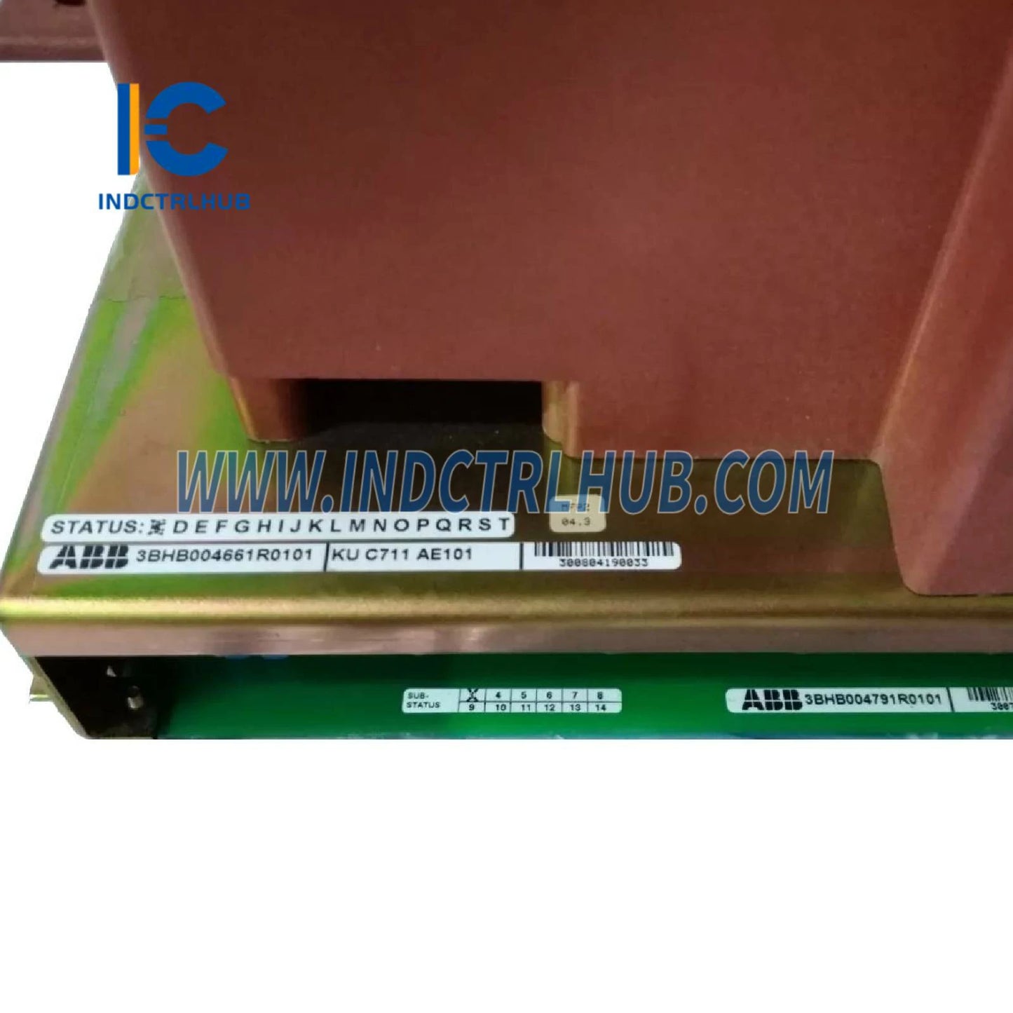
3BHB004661R0101 | ABB KU C711 AE Gate Unit Power Supply
3BHB004661R0101 | ABB KU C711 AE Gate Unit Power Supply
Manufacturer: ABB
Product No.: 3BHB004661R0101 KU C711 AE 101
Condition:1000 in stock
Product Type: Gate Unit Power Supply
Product Origin: 3004661000016
Payment: T/T, Western Union
Weight: 4700g
Shipping port: Xiamen
Warranty: 12 months
- 24/7 Support
- 30-Day Returns
- Fast Shipping
ABB KU C711 AE Gate Unit Power Supply - Critical Power Electronics for ACS1000 Drives
The ABB KU C711 AE Gate Unit Power Supply (Part Number: 3BHB004661R0101) represents a mission-critical power electronics assembly designed exclusively for ABB ACS1000 medium voltage AC drive systems. This Swiss-engineered gate driver unit delivers precision-controlled gate signals to high-power IGCT (Integrated Gate-Commutated Thyristor) modules, enabling reliable operation of multi-megawatt industrial drive applications in the most demanding process industries worldwide.
Product Identification & Specifications
| Parameter | Details |
|---|---|
| ABB Part Number | 3BHB004661R0101 |
| Type Designation | KU C711 AE |
| Product Name | Gate Unit Power Supply (GUSP) |
| Catalog Description | GATE UNIT POWER S GUSP |
| Part Type | New (Current Production) |
| Country of Origin | Switzerland (CH) |
| HS Customs Code | 85049099 |
| Net Weight | 4.7 kg |
| Minimum Order Quantity | 1 piece |
| Selling Unit | piece |
Assembly Composition & Included Components
IMPORTANT TECHNICAL NOTE: This gate unit assembly (3BHB004661R0101) includes 7 pieces of subboards with part number 3BHB003688R0101 (KU C711 AE PCB ass. varn. Subb. 20V) as integral components of the complete power supply unit. These subboards are factory-installed and tested as part of the complete assembly.
Subboard Specifications (3BHB003688R0101)
- Quantity per Gate Unit: 7 pieces (pre-installed)
- Function: Individual gate driver circuits for IGCT power modules
- Voltage Rating: 20V gate drive voltage
- PCB Treatment: Varnished for environmental protection and insulation
- Replacement: Available separately for field service and repairs
Superseded Part Numbers & Compatibility
This current-generation gate unit (3BHB004661R0101) replaces the following obsolete part numbers in existing ACS1000 installations:
- 3BHB003295R0002 - Previous generation gate unit
- 3BHB002433R0001 - Early production variant
- 3BHB003295R0001 - Intermediate revision
- HB004661R0101 - Alternative part number designation
- 3BHB004661R0001 - Initial release version
The current R0101 revision incorporates design improvements for enhanced reliability, extended component lifespan, and improved electromagnetic compatibility compared to superseded versions. Direct retrofit compatibility is maintained with all ACS1000 drive generations.
Functional Overview & Operating Principles
Gate Driver Architecture
The KU C711 AE gate unit serves as the critical interface between the ACS1000 drive's control electronics and the high-power IGCT switching devices. Each of the seven integrated subboards generates isolated, high-current gate pulses required to turn on and turn off individual IGCT modules with nanosecond-level timing precision.
Key Functional Capabilities
- Isolated Gate Drive: Galvanically isolated gate signals protect low-voltage control circuits from high-voltage power stage transients
- Precision Timing Control: Sub-microsecond gate pulse timing ensures optimal IGCT switching performance and minimizes switching losses
- Fault Detection: Integrated desaturation detection and short-circuit protection safeguard IGCTs from catastrophic failures
- Status Monitoring: Real-time feedback signals to drive controller for diagnostic and protective functions
- Power Supply Regulation: Stable gate drive voltage generation from auxiliary power inputs with wide tolerance range
- EMC Compliance: Shielded construction and filtering minimize electromagnetic emissions and susceptibility
Operating Environment
- Ambient Temperature: -10°C to +50°C (operational), -25°C to +70°C (storage)
- Humidity: 5-95% RH non-condensing
- Altitude: Up to 1000m without derating (consult factory for higher altitudes)
- Vibration Resistance: IEC 60068-2-6 compliant for industrial environments
- Pollution Degree: 2 per IEC 60664-1
Application Context: ACS1000 Medium Voltage Drive Systems
ACS1000 Drive Platform Overview
The ABB ACS1000 is a direct-torque-controlled (DTC) medium voltage AC drive designed for high-power industrial applications ranging from 315 kW to 5 MW in standard configurations, with extended power ratings available for special applications. The drive utilizes IGCT-based voltage source inverter topology for superior performance and reliability.
Typical ACS1000 Applications
| Industry Sector | Application Examples | Power Range |
|---|---|---|
| Oil & Gas | Pipeline compressors, LNG pumps, gas injection systems | 1-5 MW |
| Mining & Minerals | SAG mills, ball mills, crushers, conveyor drives | 2-5 MW |
| Metals Processing | Rolling mills, extruders, continuous casters | 1-4 MW |
| Pulp & Paper | Refiners, grinders, winders, calenders | 500 kW-3 MW |
| Water & Wastewater | High-head pumps, aeration blowers, centrifuges | 315 kW-2 MW |
| Power Generation | Boiler feed pumps, induced draft fans, FGD systems | 1-5 MW |
| Marine & Offshore | Thruster drives, ballast pumps, FPSO systems | 500 kW-3 MW |
Gate Unit Role in Drive Operation
Within the ACS1000 architecture, the KU C711 AE gate unit occupies a critical position in the power conversion chain:
- Control Signal Reception: Receives PWM switching commands from the drive's main control board
- Signal Conditioning: Amplifies and conditions control signals to gate driver levels
- Isolation & Protection: Provides galvanic isolation and implements protective interlocks
- Gate Pulse Generation: Delivers high-current gate pulses (typically 15-30A peak) to IGCT gates
- Feedback & Diagnostics: Monitors IGCT status and reports faults to drive controller
Installation & System Integration Guidelines
Pre-Installation Requirements
- ESD Protection: Handle unit with proper electrostatic discharge precautions (wrist strap, ESD mat)
- Environmental Verification: Confirm installation location meets temperature and humidity specifications
- Compatibility Check: Verify drive serial number and configuration against spare parts list
- Documentation Review: Consult ACS1000 service manual section 4.3 for detailed installation procedures
- Safety Lockout: Ensure drive is de-energized and locked out per LOTO procedures
Installation Procedure Summary
- Access Preparation: Remove drive cabinet panels and discharge DC bus capacitors (wait minimum 15 minutes)
- Old Unit Removal: Disconnect fiber optic cables, gate signal cables, and auxiliary power connections; document cable positions
- Mounting Surface Prep: Clean mounting surface and verify grounding continuity
- New Unit Installation: Mount gate unit to chassis using specified torque (M6 screws: 5 Nm)
- Cable Reconnection: Reconnect all cables per documentation; verify fiber optic cleanliness
- Grounding Verification: Confirm PE connection resistance <0.1 Ω
- Visual Inspection: Check for proper seating, no damaged components, LED indicators
Commissioning & Verification
- Power-Up Sequence: Apply auxiliary power and verify gate unit status LEDs (green = normal)
- Self-Test Execution: Run drive self-diagnostics via control panel (Menu 9.4)
- Gate Signal Verification: Use oscilloscope to verify gate pulse amplitude and timing (requires trained personnel)
- Functional Test: Perform no-load motor run test at 10% speed for 5 minutes
- Load Test: Gradually increase load to 25%, 50%, 75%, 100% rated torque with thermal monitoring
- Documentation: Record installation date, serial numbers, and test results in maintenance log
Maintenance & Troubleshooting
Preventive Maintenance Schedule
| Interval | Maintenance Tasks |
|---|---|
| Monthly | Visual inspection for LED status, check for unusual odors or discoloration |
| Quarterly | Verify cable connections tight, inspect fiber optic cables for damage |
| Annually | Thermal imaging scan, measure gate pulse parameters, clean air filters |
| Every 3 Years | Replace electrolytic capacitors (preventive), update firmware if available |
| Every 5 Years | Complete gate unit replacement recommended (based on MTBF calculations) |
Common Fault Scenarios & Diagnostics
| Symptom | Possible Cause | Diagnostic Steps | Resolution |
|---|---|---|---|
| Drive fault: Gate Unit Failure | Gate unit power supply fault, subboard failure | Check status LEDs, measure auxiliary power voltage (24VDC nominal) | Replace gate unit or faulty subboard |
| IGCT desaturation trip | Weak gate drive, IGCT degradation, load short circuit | Verify gate pulse amplitude (15-20V typical), check IGCT with curve tracer | Replace gate unit if pulses weak; replace IGCT if degraded |
| Intermittent faults | Loose connections, fiber optic contamination, EMI interference | Re-seat all connectors, clean fiber optics with lint-free wipes, check grounding | Secure connections, replace damaged fibers, improve shielding |
| Overheating | Blocked airflow, high ambient temperature, component aging | Verify fan operation, measure cabinet temperature, thermal imaging | Clean filters, improve ventilation, replace aged components |
| No gate pulses | Control signal loss, gate unit failure, interlock active | Check fiber optic link, verify enable signals, review fault log | Repair control path, replace gate unit, clear interlock condition |
Subboard Replacement Procedure
Individual subboards (3BHB003688R0101) can be replaced in the field without replacing the entire gate unit assembly:
- De-energize drive and discharge DC bus (15 minute minimum wait)
- Remove gate unit from chassis (4x M6 mounting screws)
- Identify faulty subboard using LED indicators or diagnostic codes
- Remove subboard mounting screws (2x M3 per board, torque: 0.5 Nm)
- Carefully disconnect ribbon cable and gate output connector
- Install new subboard, ensuring proper seating and connector alignment
- Reinstall gate unit and perform commissioning verification tests
Spare Parts Strategy & Inventory Recommendations
Critical Spare Parts for ACS1000 Installations
| Part Number | Description | Recommended Qty | Criticality |
|---|---|---|---|
| 3BHB004661R0101 | Complete Gate Unit Power Supply (this product) | 1 per drive | High |
| 3BHB003688R0101 | Gate driver subboard (20V) | 2-3 pieces | Medium |
| 5SHX1445H0002 | IGCT power module (example) | 1 per drive | High |
| 3BHB003041R0101 | I/O control board UFC719AE01 | 1 per drive | Medium |
Inventory Optimization Guidelines
- Single Drive Sites: Stock 1 complete gate unit + 2 subboards for rapid fault recovery
- Multi-Drive Facilities: Stock 1 gate unit per 3-5 drives + 5 subboards for fleet coverage
- Critical Process Applications: Maintain 100% spare coverage (1:1 ratio) for zero-downtime requirements
- Shelf Life Considerations: Gate units have 10-year shelf life when stored properly (cool, dry, ESD-safe)
- Obsolescence Risk: Current production status; recommend stocking before potential phase-out (monitor ABB product bulletins)
Global Availability & Logistics
ABB Stocking Locations
This gate unit is stocked at the following ABB distribution centers for rapid delivery:
- FIPSEEXPU - Finland (Europe primary hub)
- US Drive Services - United States (Americas hub)
- SGRDC002EXPU - Singapore (Asia-Pacific regional center)
- CNIAB001EXPU - China (Asia manufacturing support)
- SGIND002EXPU - Singapore (Industrial distribution)
- AUABB024EXPU - Australia (Oceania support)
Lead Time & Shipping
- Standard Delivery: 3-5 business days from nearest stocking location
- Express Shipping: Next-day delivery available for critical outages (surcharge applies)
- International Orders: 5-10 business days including customs clearance
- Packaging: ESD-safe packaging with shock-absorbing foam, export-certified wooden crate for international shipments
Technical Support & Documentation Resources
Available Documentation
- ACS1000 Technical Catalog: Complete drive system specifications and selection guide
- Service Manual: Detailed maintenance procedures, fault diagnostics, and spare parts lists
- Installation Manual: Mechanical and electrical installation instructions with wiring diagrams
- Commissioning Guide: Step-by-step startup and parameter configuration procedures
- Spare Parts Catalog: Illustrated parts breakdown with ordering information
- Application Notes: Industry-specific application guidelines and best practices
Engineering Support Services
- 24/7 Technical Hotline: Emergency support for critical drive failures
- Remote Diagnostics: Online troubleshooting via drive communication interface
- Field Service: On-site installation, commissioning, and repair services available globally
- Training Programs: Operator and maintenance training courses at ABB training centers
- Retrofit & Upgrade Services: Modernization of older ACS1000 installations with current-generation components
Quality Assurance & Warranty Coverage
Manufacturing Quality Standards
- Production Facility: Manufactured in ABB's ISO 9001:2015 certified Swiss facility
- Component Sourcing: Automotive-grade components with extended temperature ratings
- Testing Protocol: 100% functional test including burn-in cycle, gate pulse verification, and isolation testing
- Traceability: Full component-level traceability with serialized production records
- Quality Certifications: CE marked, UL recognized, IEC 61800-5-1 compliant
Warranty Terms
- Standard Warranty: 24 months from date of shipment for manufacturing defects
- Extended Warranty: Available up to 60 months with ABB service agreement
- Warranty Exclusions: Damage from improper installation, environmental contamination, or electrical overstress
- Return Policy: Unused units returnable within 30 days (restocking fee may apply)
- Repair Services: Factory repair available for out-of-warranty units (quote upon inspection)
Reliability Data
- MTBF (Mean Time Between Failures): >150,000 hours at 40°C ambient
- Design Life: 15 years under normal operating conditions
- Failure Rate: <0.5% annual failure rate in field installations
- Field Performance: Proven in >5,000 ACS1000 drive installations worldwide since 2006
Environmental Compliance & Disposal
- RoHS Compliance: Fully compliant with EU RoHS Directive 2011/65/EU (lead-free manufacturing)
- REACH Compliance: No substances of very high concern (SVHC) above threshold limits
- WEEE Directive: Recyclable electronic waste - return to ABB or authorized recycler for proper disposal
- Conflict Minerals: Sourced from conflict-free suppliers per Dodd-Frank Act requirements
- Environmental Product Declaration: Available upon request for LEED and sustainability reporting
Procurement & Ordering Information
How to Order
- Part Number Verification: Confirm 3BHB004661R0101 matches your drive's spare parts list
- Quantity Selection: Minimum order quantity is 1 piece (no order multiples required)
- Delivery Preference: Specify standard or express shipping based on urgency
- Documentation Needs: Request certificates of conformity, test reports, or calibration data if required
- Contact Information: Provide complete shipping address and technical contact for delivery coordination
Pricing & Payment Terms
- List Price: Contact for current pricing (subject to change based on exchange rates and material costs)
- Volume Discounts: Available for orders of 5+ units or annual purchase agreements
- Payment Terms: Net 30 days for established accounts, prepayment for new customers
- Currency: USD, EUR, or local currency accepted
- Export Compliance: Subject to Swiss and international export control regulations


Product Description
ABB KU C711 AE Gate Unit Power Supply - Critical Power Electronics for ACS1000 Drives
The ABB KU C711 AE Gate Unit Power Supply (Part Number: 3BHB004661R0101) represents a mission-critical power electronics assembly designed exclusively for ABB ACS1000 medium voltage AC drive systems. This Swiss-engineered gate driver unit delivers precision-controlled gate signals to high-power IGCT (Integrated Gate-Commutated Thyristor) modules, enabling reliable operation of multi-megawatt industrial drive applications in the most demanding process industries worldwide.
Product Identification & Specifications
| Parameter | Details |
|---|---|
| ABB Part Number | 3BHB004661R0101 |
| Type Designation | KU C711 AE |
| Product Name | Gate Unit Power Supply (GUSP) |
| Catalog Description | GATE UNIT POWER S GUSP |
| Part Type | New (Current Production) |
| Country of Origin | Switzerland (CH) |
| HS Customs Code | 85049099 |
| Net Weight | 4.7 kg |
| Minimum Order Quantity | 1 piece |
| Selling Unit | piece |
Assembly Composition & Included Components
IMPORTANT TECHNICAL NOTE: This gate unit assembly (3BHB004661R0101) includes 7 pieces of subboards with part number 3BHB003688R0101 (KU C711 AE PCB ass. varn. Subb. 20V) as integral components of the complete power supply unit. These subboards are factory-installed and tested as part of the complete assembly.
Subboard Specifications (3BHB003688R0101)
- Quantity per Gate Unit: 7 pieces (pre-installed)
- Function: Individual gate driver circuits for IGCT power modules
- Voltage Rating: 20V gate drive voltage
- PCB Treatment: Varnished for environmental protection and insulation
- Replacement: Available separately for field service and repairs
Superseded Part Numbers & Compatibility
This current-generation gate unit (3BHB004661R0101) replaces the following obsolete part numbers in existing ACS1000 installations:
- 3BHB003295R0002 - Previous generation gate unit
- 3BHB002433R0001 - Early production variant
- 3BHB003295R0001 - Intermediate revision
- HB004661R0101 - Alternative part number designation
- 3BHB004661R0001 - Initial release version
The current R0101 revision incorporates design improvements for enhanced reliability, extended component lifespan, and improved electromagnetic compatibility compared to superseded versions. Direct retrofit compatibility is maintained with all ACS1000 drive generations.
Functional Overview & Operating Principles
Gate Driver Architecture
The KU C711 AE gate unit serves as the critical interface between the ACS1000 drive's control electronics and the high-power IGCT switching devices. Each of the seven integrated subboards generates isolated, high-current gate pulses required to turn on and turn off individual IGCT modules with nanosecond-level timing precision.
Key Functional Capabilities
- Isolated Gate Drive: Galvanically isolated gate signals protect low-voltage control circuits from high-voltage power stage transients
- Precision Timing Control: Sub-microsecond gate pulse timing ensures optimal IGCT switching performance and minimizes switching losses
- Fault Detection: Integrated desaturation detection and short-circuit protection safeguard IGCTs from catastrophic failures
- Status Monitoring: Real-time feedback signals to drive controller for diagnostic and protective functions
- Power Supply Regulation: Stable gate drive voltage generation from auxiliary power inputs with wide tolerance range
- EMC Compliance: Shielded construction and filtering minimize electromagnetic emissions and susceptibility
Operating Environment
- Ambient Temperature: -10°C to +50°C (operational), -25°C to +70°C (storage)
- Humidity: 5-95% RH non-condensing
- Altitude: Up to 1000m without derating (consult factory for higher altitudes)
- Vibration Resistance: IEC 60068-2-6 compliant for industrial environments
- Pollution Degree: 2 per IEC 60664-1
Application Context: ACS1000 Medium Voltage Drive Systems
ACS1000 Drive Platform Overview
The ABB ACS1000 is a direct-torque-controlled (DTC) medium voltage AC drive designed for high-power industrial applications ranging from 315 kW to 5 MW in standard configurations, with extended power ratings available for special applications. The drive utilizes IGCT-based voltage source inverter topology for superior performance and reliability.
Typical ACS1000 Applications
| Industry Sector | Application Examples | Power Range |
|---|---|---|
| Oil & Gas | Pipeline compressors, LNG pumps, gas injection systems | 1-5 MW |
| Mining & Minerals | SAG mills, ball mills, crushers, conveyor drives | 2-5 MW |
| Metals Processing | Rolling mills, extruders, continuous casters | 1-4 MW |
| Pulp & Paper | Refiners, grinders, winders, calenders | 500 kW-3 MW |
| Water & Wastewater | High-head pumps, aeration blowers, centrifuges | 315 kW-2 MW |
| Power Generation | Boiler feed pumps, induced draft fans, FGD systems | 1-5 MW |
| Marine & Offshore | Thruster drives, ballast pumps, FPSO systems | 500 kW-3 MW |
Gate Unit Role in Drive Operation
Within the ACS1000 architecture, the KU C711 AE gate unit occupies a critical position in the power conversion chain:
- Control Signal Reception: Receives PWM switching commands from the drive's main control board
- Signal Conditioning: Amplifies and conditions control signals to gate driver levels
- Isolation & Protection: Provides galvanic isolation and implements protective interlocks
- Gate Pulse Generation: Delivers high-current gate pulses (typically 15-30A peak) to IGCT gates
- Feedback & Diagnostics: Monitors IGCT status and reports faults to drive controller
Installation & System Integration Guidelines
Pre-Installation Requirements
- ESD Protection: Handle unit with proper electrostatic discharge precautions (wrist strap, ESD mat)
- Environmental Verification: Confirm installation location meets temperature and humidity specifications
- Compatibility Check: Verify drive serial number and configuration against spare parts list
- Documentation Review: Consult ACS1000 service manual section 4.3 for detailed installation procedures
- Safety Lockout: Ensure drive is de-energized and locked out per LOTO procedures
Installation Procedure Summary
- Access Preparation: Remove drive cabinet panels and discharge DC bus capacitors (wait minimum 15 minutes)
- Old Unit Removal: Disconnect fiber optic cables, gate signal cables, and auxiliary power connections; document cable positions
- Mounting Surface Prep: Clean mounting surface and verify grounding continuity
- New Unit Installation: Mount gate unit to chassis using specified torque (M6 screws: 5 Nm)
- Cable Reconnection: Reconnect all cables per documentation; verify fiber optic cleanliness
- Grounding Verification: Confirm PE connection resistance <0.1 Ω
- Visual Inspection: Check for proper seating, no damaged components, LED indicators
Commissioning & Verification
- Power-Up Sequence: Apply auxiliary power and verify gate unit status LEDs (green = normal)
- Self-Test Execution: Run drive self-diagnostics via control panel (Menu 9.4)
- Gate Signal Verification: Use oscilloscope to verify gate pulse amplitude and timing (requires trained personnel)
- Functional Test: Perform no-load motor run test at 10% speed for 5 minutes
- Load Test: Gradually increase load to 25%, 50%, 75%, 100% rated torque with thermal monitoring
- Documentation: Record installation date, serial numbers, and test results in maintenance log
Maintenance & Troubleshooting
Preventive Maintenance Schedule
| Interval | Maintenance Tasks |
|---|---|
| Monthly | Visual inspection for LED status, check for unusual odors or discoloration |
| Quarterly | Verify cable connections tight, inspect fiber optic cables for damage |
| Annually | Thermal imaging scan, measure gate pulse parameters, clean air filters |
| Every 3 Years | Replace electrolytic capacitors (preventive), update firmware if available |
| Every 5 Years | Complete gate unit replacement recommended (based on MTBF calculations) |
Common Fault Scenarios & Diagnostics
| Symptom | Possible Cause | Diagnostic Steps | Resolution |
|---|---|---|---|
| Drive fault: Gate Unit Failure | Gate unit power supply fault, subboard failure | Check status LEDs, measure auxiliary power voltage (24VDC nominal) | Replace gate unit or faulty subboard |
| IGCT desaturation trip | Weak gate drive, IGCT degradation, load short circuit | Verify gate pulse amplitude (15-20V typical), check IGCT with curve tracer | Replace gate unit if pulses weak; replace IGCT if degraded |
| Intermittent faults | Loose connections, fiber optic contamination, EMI interference | Re-seat all connectors, clean fiber optics with lint-free wipes, check grounding | Secure connections, replace damaged fibers, improve shielding |
| Overheating | Blocked airflow, high ambient temperature, component aging | Verify fan operation, measure cabinet temperature, thermal imaging | Clean filters, improve ventilation, replace aged components |
| No gate pulses | Control signal loss, gate unit failure, interlock active | Check fiber optic link, verify enable signals, review fault log | Repair control path, replace gate unit, clear interlock condition |
Subboard Replacement Procedure
Individual subboards (3BHB003688R0101) can be replaced in the field without replacing the entire gate unit assembly:
- De-energize drive and discharge DC bus (15 minute minimum wait)
- Remove gate unit from chassis (4x M6 mounting screws)
- Identify faulty subboard using LED indicators or diagnostic codes
- Remove subboard mounting screws (2x M3 per board, torque: 0.5 Nm)
- Carefully disconnect ribbon cable and gate output connector
- Install new subboard, ensuring proper seating and connector alignment
- Reinstall gate unit and perform commissioning verification tests
Spare Parts Strategy & Inventory Recommendations
Critical Spare Parts for ACS1000 Installations
| Part Number | Description | Recommended Qty | Criticality |
|---|---|---|---|
| 3BHB004661R0101 | Complete Gate Unit Power Supply (this product) | 1 per drive | High |
| 3BHB003688R0101 | Gate driver subboard (20V) | 2-3 pieces | Medium |
| 5SHX1445H0002 | IGCT power module (example) | 1 per drive | High |
| 3BHB003041R0101 | I/O control board UFC719AE01 | 1 per drive | Medium |
Inventory Optimization Guidelines
- Single Drive Sites: Stock 1 complete gate unit + 2 subboards for rapid fault recovery
- Multi-Drive Facilities: Stock 1 gate unit per 3-5 drives + 5 subboards for fleet coverage
- Critical Process Applications: Maintain 100% spare coverage (1:1 ratio) for zero-downtime requirements
- Shelf Life Considerations: Gate units have 10-year shelf life when stored properly (cool, dry, ESD-safe)
- Obsolescence Risk: Current production status; recommend stocking before potential phase-out (monitor ABB product bulletins)
Global Availability & Logistics
ABB Stocking Locations
This gate unit is stocked at the following ABB distribution centers for rapid delivery:
- FIPSEEXPU - Finland (Europe primary hub)
- US Drive Services - United States (Americas hub)
- SGRDC002EXPU - Singapore (Asia-Pacific regional center)
- CNIAB001EXPU - China (Asia manufacturing support)
- SGIND002EXPU - Singapore (Industrial distribution)
- AUABB024EXPU - Australia (Oceania support)
Lead Time & Shipping
- Standard Delivery: 3-5 business days from nearest stocking location
- Express Shipping: Next-day delivery available for critical outages (surcharge applies)
- International Orders: 5-10 business days including customs clearance
- Packaging: ESD-safe packaging with shock-absorbing foam, export-certified wooden crate for international shipments
Technical Support & Documentation Resources
Available Documentation
- ACS1000 Technical Catalog: Complete drive system specifications and selection guide
- Service Manual: Detailed maintenance procedures, fault diagnostics, and spare parts lists
- Installation Manual: Mechanical and electrical installation instructions with wiring diagrams
- Commissioning Guide: Step-by-step startup and parameter configuration procedures
- Spare Parts Catalog: Illustrated parts breakdown with ordering information
- Application Notes: Industry-specific application guidelines and best practices
Engineering Support Services
- 24/7 Technical Hotline: Emergency support for critical drive failures
- Remote Diagnostics: Online troubleshooting via drive communication interface
- Field Service: On-site installation, commissioning, and repair services available globally
- Training Programs: Operator and maintenance training courses at ABB training centers
- Retrofit & Upgrade Services: Modernization of older ACS1000 installations with current-generation components
Quality Assurance & Warranty Coverage
Manufacturing Quality Standards
- Production Facility: Manufactured in ABB's ISO 9001:2015 certified Swiss facility
- Component Sourcing: Automotive-grade components with extended temperature ratings
- Testing Protocol: 100% functional test including burn-in cycle, gate pulse verification, and isolation testing
- Traceability: Full component-level traceability with serialized production records
- Quality Certifications: CE marked, UL recognized, IEC 61800-5-1 compliant
Warranty Terms
- Standard Warranty: 24 months from date of shipment for manufacturing defects
- Extended Warranty: Available up to 60 months with ABB service agreement
- Warranty Exclusions: Damage from improper installation, environmental contamination, or electrical overstress
- Return Policy: Unused units returnable within 30 days (restocking fee may apply)
- Repair Services: Factory repair available for out-of-warranty units (quote upon inspection)
Reliability Data
- MTBF (Mean Time Between Failures): >150,000 hours at 40°C ambient
- Design Life: 15 years under normal operating conditions
- Failure Rate: <0.5% annual failure rate in field installations
- Field Performance: Proven in >5,000 ACS1000 drive installations worldwide since 2006
Environmental Compliance & Disposal
- RoHS Compliance: Fully compliant with EU RoHS Directive 2011/65/EU (lead-free manufacturing)
- REACH Compliance: No substances of very high concern (SVHC) above threshold limits
- WEEE Directive: Recyclable electronic waste - return to ABB or authorized recycler for proper disposal
- Conflict Minerals: Sourced from conflict-free suppliers per Dodd-Frank Act requirements
- Environmental Product Declaration: Available upon request for LEED and sustainability reporting
Procurement & Ordering Information
How to Order
- Part Number Verification: Confirm 3BHB004661R0101 matches your drive's spare parts list
- Quantity Selection: Minimum order quantity is 1 piece (no order multiples required)
- Delivery Preference: Specify standard or express shipping based on urgency
- Documentation Needs: Request certificates of conformity, test reports, or calibration data if required
- Contact Information: Provide complete shipping address and technical contact for delivery coordination
Pricing & Payment Terms
- List Price: Contact for current pricing (subject to change based on exchange rates and material costs)
- Volume Discounts: Available for orders of 5+ units or annual purchase agreements
- Payment Terms: Net 30 days for established accounts, prepayment for new customers
- Currency: USD, EUR, or local currency accepted
- Export Compliance: Subject to Swiss and international export control regulations